


Aimayo, J. V., Dibosa, P., & Olorunwaju, A. (2026). Design and Development of A 1.5 KVA Mobile Solar Power System as an Alternative Power Supply for Teaching and Learning. International Journal of Research, 13(1), 269–277. https://doi.org/10.26643/ijr/2026/5
Engr. J.V. Aimayo (Phd)
Engr. P. Dibosa
Department of Electrical/ Electronic Technology Education
Mr. A. Olorunwaju
Department of Automobile Technology Education
Federal College of Education, Technical, Asaba
Abstract
This project involved designing and developing a 1.5 KVA solar power system as an alternative power source for teaching and learning. It was initiated to address the major challenge of inadequate and unreliable power supply at the Federal College of Education Technical Asaba. The study employed a design and development approach following standard engineering stages, including problem identification, system specification, design analysis, component selection, construction, and performance testing. Materials used included four 250W solar panels, 60 Amps, MPPT charge controller, a 240 Ah deep-cycle battery, and a 1.5 KVA inverter. These components were assembled into the system. The inverter’s performance was evaluated through various tests: a no-load test to verify output voltage and frequency, a load test using instructional equipment to assess stability, and a battery discharge test to determine backup duration. Additional tests on mobility and safety assessed ease of movement and compliance with electrical safety standards. Test results were compared with the design specifications to evaluate effectiveness for educational purposes. During the no-load test, the inverter produced approximately 230 V AC at 50 Hz, meeting standard utility requirements. At an estimated load of 484 W, about 80% of the inverter’s rated capacity, the output remained stable without shutdown or overheating, indicating suitability for continuous use in classrooms and labs. The battery discharge test showed an average backup of 3.5 to 4.1 hours under full instructional load, closely matching the estimated backup time during design.
Keywords: MPPT, Load, Design, Test
Introduction
Electricity plays a vital role in modern society and has become an indispensable resource across virtually all aspects of human endeavor. Access to reliable electrical power enables educational, economic, industrial, and technological activities, thereby enhancing productivity and quality of life. Unfortunately, consistent access to electricity remains a major challenge in many developing countries, including Nigeria. Despite successive administrations investing substantial financial resources in electricity generation, transmission, and distribution projects, the supply of power in Nigeria continues to be inadequate in both quantity and quality.
As a result of frequent power outages and unreliable grid supply, many households and business owners have resorted to the use of diesel-powered generators as alternative sources of electricity. While generators provide temporary relief, their use is associated with several disadvantages, including high operating and maintenance costs, excessive noise pollution, and adverse environmental and health impacts due to exhaust emissions. These challenges underscore the urgent need for clean, sustainable, and cost-effective alternative energy sources.
Renewable energy, particularly solar photovoltaic (PV) technology, presents a viable solution to these challenges. Solar PV systems are renewable, environmentally friendly, silent in operation, and suitable for both grid-connected and off-grid applications. In recent years, the integration of solar PV systems into educational environments has gained increasing attention, especially in regions characterized by unstable or inadequate electricity supply. Solar PV systems are particularly attractive for educational institutions due to their scalability, declining installation costs, and long-term economic benefits.
Several studies have demonstrated the effectiveness of solar PV systems in meeting institutional energy needs. For instance, Okpeki et al. (2023) evaluated a 2.5 kVA solar power system and established its viability in supplying basic electrical loads through appropriate sizing of solar panels, charge controllers, batteries, and inverters. Extending these design principles to moderate-capacity systems, Mbaya et al. (2022) reported the design and implementation of a 5 kVA solar photovoltaic system for an electronics laboratory. Their study showed that the system was capable of delivering over 18 kWh of energy daily, ensuring uninterrupted laboratory activities and reliable power supply for critical teaching equipment during grid outages. Similarly, Yunisa et al. (2022) emphasized the importance of effective power electronics design in the construction of a 5 kVA solar power inverter system, highlighting the need for reliable DC–AC conversion and system protection to support sensitive educational equipment.
Beyond fixed installations, mobile solar power systems offer additional advantages, particularly in teaching and learning contexts that require flexibility and portability. Mobile systems introduce design considerations such as weight distribution, structural housing, ease of deployment, and maintenance, which are essential for practical educational use. Against this backdrop, the main purpose of this study is to design and develop a 1.5 kVA mobile solar power system as an alternative power supply for teaching and learning. The specific objectives include problem identification, system specification, design analysis, component selection, construction, and performance testing.
The scope of the study covers the design, construction, and testing of a 1.5 kVA mobile solar generator comprising solar panels, batteries, a charge controller, an inverter, a protective casing, and a mobile trolley. Upon completion, the system is expected to provide a clean, silent, and reliable source of electricity for academic activities, while also enhancing students’ acquisition of practical technical skills through hands-on engagement with renewable energy technologies.
MATERIALS AND METHOD
Materials for the development of the mobile solar power system include solar panels, assorted cables charge controller, a battery bank, an inverter unit, and mobile mechanical enclosure. The quantities, ratings, dimensions, and capacities of these materials are determined by a simple engineering design procedure .Materials were acquired from local electrical/ electronic shops within the area of study. The block diagram of the system is shown in figure 1 .
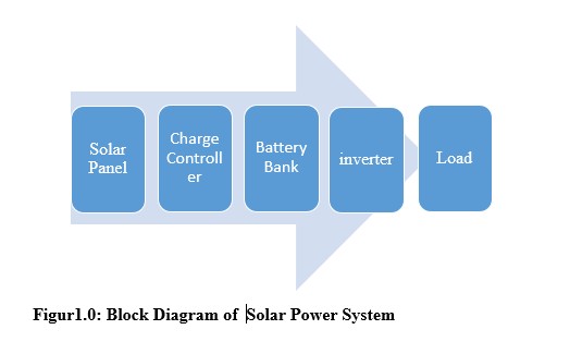
Figur1.0: Block Diagram of Solar Power System
System Design Procedure
This study adopted a design-and-development research design. The methodology followed standard engineering design stages, including problem identification, system specification, design analysis, component selection, construction, and performance testing. Based on loads assessment, the system has the following specifications; 1.5KVA, 230V output AC, 50Hz, with minimum efficiency of 80%. In order to determine ratings, capacity, dimensions and quantities of different sub-units, basic engineering design procedure were employed in designing different units as shown in the following section .
Inverter Unit Design
The estimated total power demand was calculated, as shown in Table 1.
Table: Load and their ratings
| Appliances | Unit Rating | Quantity | Total Rating |
| Desktop Computer | 25 | 4 | 100 |
| Lighting Point | 15 | 5 | 75 |
| Ceiling Fans | 70 | 2 | 140 |
| Phones & Laptops | Assorted | – | 10 |
| Projector | 40 | 1 | 50 |
| Safety Margin | 30% | 90 |
Total load was determined using Equation (1)
Total load (TL) = (Total Rating) (1)
TL = 605W
The inverter’s apparent power rating was determined using Equation (2), assuming a power factor of 0.8:
KVA = (2)
= 0.756KVA
This value requires selecting a 1.5 kVA inverter to accommodate load fluctuations and ensure safe operation.
Battery Bank Design
The battery capacity required to support the inverter system was calculated using Equation (3):or (4)
(3)
Wh = (4)
Where Ah and Wh are the battery capacity, P is the load power, V is the battery Voltage, η is the inverter efficiency, and DOD is debt of discharge. Assuming a load of 605W, a backup time of 4 hours, a battery voltage of 12V, efficiency of 85% and DOD is 50% for lead acid batteries.
Battery capacity of approximately 237Ah was obtained.
Consequently, a 12 V, 250 Ah deep-cycle battery was selected.
Charging System Design
The battery charging current was selected based on 10–20% of the battery capacity, as expressed in Equation (5):
I charge = 0.1 Ah
A charging current of approximately 25 A was obtained, leading to the selection of a 12 V, 30 A smart battery charger to ensure efficient and safe charging.
Solar Panel Array Design
Solar panel power was determined based on total battery voltage, battery capacity, and peak sun -hour.
Solar Panel Power ![]() =
= (6)
Where V is the total battery voltage, 12V, Ah is the battery capacity, 250, η is the controller efficiency, 0.85, and PSH is the daily sun-hours, 5hrs. Substituting values into (6) above,
required panel capacity ≈ 352 W
Selected panels: 250 W × 2 = 500 W
Charge Controller Design
2 panels, each with Isc = 8.5A
Total I (2 parallel strings x 8.5 A) = 17A
Apply 25% safety margin = 17.5 x 1.25 (21.9A)
Icontroller = 39.1A
Minimum I controller = 45A Controller
Cable Sizing Design
Different sizes of cables were used for the connections. Selection was based on current ratings of the system. Cable carrying 40A current from solar panel array to charge controller according to IEEE standard is 6mm2. 25A Charging current from charge controller to battery bank is 2.5mm2. .
MOBILE MECHANICAL ENCLOSURE CONSTRUCTION
The inverter system’s mechanical structure was designed for improved portability and safety. A steel enclosure was built to securely hold the inverter unit and battery. Ventilation slots and cooling fans were added to help manage heat during operation. Four durable caster wheels were attached to the base of the enclosure, allowing easy movement across classrooms, laboratories, workshops, and other settings.
Dimension of Mechanical Enclosure
| Parameter | Specification |
| Height | 635 mm |
| Width | 420 mm |
| Depth | 620 mm |
| Material | Mild steel |
| Sheet thickness | 0.3 mm |
| Cooling fan | 80 mm DC fan |
| Vent holes | Ø4 mm |
| Mounting | Wall-mounted |
COMPONENT SELECTION AND DEVELOPMENT
Having determined the ratings, capacity and quantities of different components of the power system, A 1.5KVA Inverter Module, 12V, 250 Ah Deep cycle battery, Protective devices, cooling Fans and a ventilated steel casing with caster wheel were selected. The system was assembled following standard electrical safety practices
TESTING AND PERFORMANCE EVALUATION
The performance of the developed inverter system was evaluated through a series of tests. These included a no-load test to verify output voltage and frequency, a load test using instructional equipment to assess system stability, and a battery discharge test to determine backup duration. Mobility and safety tests were also conducted to assess ease of movement and compliance with electrical safety requirements. See Table 2.
Table 2: Testing and Performance Evaluation
| S/N | Type of test | Test Procedure | Result |
| 1 | Visual Test | Checked cable tightness and insulation | Cable joints are firm and intact |
| 2 | No load Test | All loads were disconnected from the inverter output. The output voltage and frequency were measured. | 220 V AC and 50 Hz Respectively |
| 3 | Load Test | Approximately 80% of the loads were connected to the inverter output. Output voltage and frequency values were measured | 230V , 50HZ |
| 4 | Battery discharge test | Approximately 80% of the loads were connected to the inverter output, and the DC voltage reading was taken at intervals | It took about 4.3 – 4-8 hours to discharge – |
| 4 | Insulation Resistance Test | Live–Earth, Neutral–Earth | ≥1 MΩ |
| 5 | Mobility and safety tests | The inverter system with rollers was pushed around within the teaching location | There was free movement across different floor structure |
ANALYSIS/ DISCUSSION.
The developed mobile 1.5 kVA inverter system was subjected to a series of performance tests, including no-load, load, battery-discharge, and mobility evaluations. The results were compared with the design specifications to assess the system’s effectiveness for teaching and learning applications.
During the no-load test, the inverter produced an output voltage of approximately 230 V AC at 50 Hz, which conforms to standard utility supply requirements. Voltage fluctuations were minimal and remained within the ±5 % tolerance range, indicating stable inverter operation under no-load conditions.
Under load conditions, the inverter system successfully powered instructional equipment, including desktop computers, a multimedia projector, LED lighting, and laboratory equipment. At an estimated load of 484 corresponding to 80% of the inverter’s rated capacity, the output voltage remained stable, with no observable system shutdown or overheating. This demonstrates the inverter’s suitability for continuous academic use in classrooms and laboratories.
The 12 V, 250 Ah deep-cycle battery’s discharge test demonstrated an average backup duration of approximately 3.5 -4.1 hours under full instructional load. This closely aligns with the theoretical backup time estimated during the design phase. Minor differences in backup time were caused by factors like internal battery resistance, ambient temperature, and load variations. The strong correlation between predicted and actual results validates the battery sizing method employed. The backup time achieved is sufficient for standard lecture periods, lab sessions, and practical demonstrations, thereby helping minimize instructional disruptions from power outages.
CONCLUSION
This study was designed to develop a 1.5 kVA mobile solar power system as an alternative power supply for teaching and learning, with application to the Federal College of Education (Technical), Asaba. System specification, design analysis, component selection, construction, and performance testing were carried out, and the measured results closely aligned with the design specifications. The strong agreement between predicted and actual performance confirms the system’s reliability and suitability for continuous academic use where load demand does not exceed 1.5 kVA.
In addition to improving power availability for instructional activities, the project provides practical exposure for students to renewable energy system design and application, thereby supporting technical skill development in educational institutions.
References
Abubakar, I. N., Idoko, J. A., Dodo, U. A., Umar, A., Zarmai, J. T., Abubakar, M., & Ndagi, U. (2023). Design and implementation of a 1.5 kVA solar powered mobile inverter. ATBU Journal of Science, Technology and Education.
Ahmad, S., Hasan, S. M. N., Hossain, M. S., Uddin, R., Ahmed, T., Mustayen, A. G. M. B., … Saha, A. A. (2024). A review of hybrid renewable and sustainable power supply system: Unit sizing, optimization, control, and management. Energies, 17(23), 6027.
Bakri, J. A., Badmus, I., & Hammed, S. O. (2022). Comparative assessment of solar photovoltaic system and diesel generating set for energy sustainability in engineering buildings of Yaba College of Technology. European Journal of Energy Research.
Mbaya, E., Omiloli, K. A., Anagor, K., Ekong, K. K., Esisio, E., Obiazi, O., … Samuel, I. A. (2022). Design and implementation of a 5 kVA solar photovoltaic system for the Electronics Laboratory in Covenant University (Conference Paper).
Mutalub, A., Ogunbiyi, O., & Makinde, K. (2023). Design, implementation and performance analysis of an off-grid solar powered system for a Nigerian household. MethodsX.
Okpeki, U. K., Oyubu, O., Efenedo, G. I., Adegoke, A. S., & Aloamaka, A. C. (2023). Design and implementation of a 2.5 kVA solar power system. International Journal of Recent Engineering Science, 10(4), 48–57.
Yunisa, Y., Zhimwang, J. T., Ibrahim, A., Shaka, O. S., & Frank, L. M. (2022). Design and construction of 5 kVA solar power inverter system. International Journal of Advances in Engineering and Management, 4(2), 1355–1358

You must be logged in to post a comment.