Switching to solar energy is a significant investment, making it essential to choose the right team for the job. With the growing demand for renewable energy, more homeowners and businesses are turning to the trusted experts among solar power companies in Utah. Partnering with a reliable solar provider guarantees high-quality results, long-term savings, and lasting peace of mind. Here’s a guide to help you make an informed decision.
Before contacting a solar company, it’s essential to clearly define your needs. Are you installing solar panels for a residential home, a commercial property, or an off-grid site? Knowing the size, scope, and goals of your project will help you identify a team with the right expertise for your installation. When discussing your requirements, be sure to ask potential providers about their experience with similar projects. This will give you a better sense of whether they have the skills and knowledge to meet your specific needs.
Research Solar Power Companies Carefully
Finding the right team starts with thorough research. Focus on companies with a strong reputation in your area and beyond. Customer reviews, industry certifications, and local awards can offer valuable insight into their credibility. Additionally, review their portfolio of completed projects to assess their expertise. A reliable team will showcase a proven track record of successful installations that align with your expectations for quality and scale.
Prioritize Local Expertise
Working with a local solar company offers significant advantages, thanks to their familiarity with the climate, regulations, and available incentives in your area. These experts understand the unique challenges of the local environment, such as snow load requirements and the ideal panel angles for maximum sun exposure. Their in-depth knowledge not only ensures a more efficient and effective solar installation but also helps you take full advantage of state and federal tax incentives, saving you more money in the long run.
Ask About Licensing, Insurance, and Warranties
Choosing licensed and insured solar power companies ensures your protection throughout the installation process. Always verify that the team holds the required state licenses and adequate insurance, safeguarding you from liability in case of accidents. Additionally, inquire about warranties on both equipment and labor. A reliable company stands by its work, offering warranties that demonstrate their commitment to quality and customer satisfaction.
Evaluate Communication and Transparency
Effective communication is essential to the success of any solar project. A reliable team will take the time to address your questions, clearly outline the process, and keep you informed every step of the way. Transparency in pricing, timelines, and expectations demonstrates a commitment to honesty and customer satisfaction. Trustworthy companies also proactively discuss potential challenges and their solutions, ensuring you feel confident and supported throughout the entire journey.
Compare Quotes Thoughtfully
While it might be tempting to select the lowest bid, it’s essential to look beyond the price tag. Take the time to review each quote thoroughly to understand what’s included. Pay attention to factors such as equipment quality, warranty terms, project timelines, and post-installation support. Investing a little more upfront in a reputable team can lead to significant savings down the road by reducing maintenance costs, minimizing repairs, and maximizing energy efficiency.
Look for Comprehensive Services
Many solar power companies go beyond basic installation, offering a comprehensive range of services. Opting for a team that handles design, permitting, installation, and ongoing maintenance ensures seamless support at every stage. A full-service provider simplifies the process, minimizes the chance of miscommunication between contractors, and delivers a smoother, more efficient experience.
Conclusion
Trust your instincts when selecting a team for your solar project. If a company appears rushed, evasive, or overly pushy in its sales tactics, it’s likely not the right fit. A reliable solar partner will prioritize respect, provide clear and thorough answers to your questions, and focus on crafting a solution tailored to your specific needs—not just closing a sale. The sun offers limitless energy potential, and partnering with the right team can transform your solar experience. By choosing a dependable solar company, you protect your investment and ensure your energy goals are met with efficiency and care.
Imagine the level of frustration if voltage fluctuations damage a new, expensive electronic device you bought. The unstable power supply is the real threat.
To tackle this threat, there is only one solution: a servo stabilizer.
The machine protects your sensitive devices from voltage fluctuations and increases the electronics’ lifespan.
With the wide range of servo stabilisersStabilizers available in the market, it can be challenging to decide which one to choose. So let’s delve into India’s top brands for servo Stabilizers.
Which company is best for servo stabilizer?
If you search for the best company offering servo Stabilizers, then Servo Stabiliser India will stand out as the most reliable, boasting the highest Google rating and customer reviews.
Their reputation as the top brand in India has been growing for the last 30 years.
Still, it is important to consider your needs, budget, and after-sales services before making an informed decision.
1. Servo Stabiliser of India
Servo Stabiliser India has you covered if you want tailored and specialised solutions. Known for energy-efficient designs tailored particularly for your sector needs, they… Their sophisticated servo technology guarantees dependable and consistent performance.
Furthermore, should any problems arise, their outstanding after-sales support will assist you.
2. Purevolt India
Whether for homes or businesses, Purevolt India is well-known for its high-quality servo Stabilizers.
Their small but strong design, exact voltage correction skills, and great industry knowledge distinguish them from others. Purevolt guarantees you are never left stranded with a nationwide service network.
3. Servokon
When dependability and durability are your main concerns, Servokon holds firm.
Perfect for heavy-duty use, their Stabilizers guarantee seamless operation even under severe circumstances by means of automatic voltage control.
If you operate big industrial machinery, this is a reliable selection.
4. Microtek
Known for its user-friendly designs, Microtek is well-known and respected all throughout India.
Perfect if you’re not a tech-savvy user, their servo Stabilizers offer great efficiency, digital displays for simple monitoring, and operational simplicity.
5. V-Guard
V-Guard, a brand well known for consumer electronics, provides value without sacrificing quality.
Their Stabilizers promise dependability and consistent performance with a wide product range suited to different consumer needs, particularly perfect for home use.
6. Servomax Ltd.
Servomax Limited is outstanding for heavy industrial needs.
Renowned for their robust and exacting servo Stabilizers, they can easily handle tough industrial settings. Built to last, their goods guarantee exact voltage control.
7. VCS India: Voltage Control & Stabilizers
With creative ideas and cutting technology, VCS India is fast establishing its presence.
Their emphasis is on tailored servo Stabilizers meant to improve performance and energy economy. A wonderful option if you want something catered to your particular needs.
Factors to Consider When Choosing a Servo Stabilizer
Picking the right servo stabilizer is something more than brand value and reputation.
Here we are listing some of the crucial factors to consider before buying the right servo stabilizer:
Power capacity: It should match your power requirement.
Type of load: Load tolerance must be slightly more than the total load your devices induce, regardless of whether you are using it for residential or industrial purposes.
Reliability & efficiency: It must be reliable enough to be efficient for a long duration.
After Sales Support: It must be fast and prompt to save you from the frustration of downtime.
Warranty: Before buying a servo stabilizer, make sure it comes with a standardised warranty.
Wrapping Up
Selecting the appropriate servo stabilizer will help you to avoid needless downtime and expensive damages.
Investing in trusted brands like Servo Stabilizer India and Purevolt India guarantees consistent performance and peace of mind.
Choose carefully to safeguard your priceless equipment right now.
Ready to choose?
Visit the official sites or contact approved dealers of these companies for individual advice suited to your requirements.
Coal India Limited (CIL) has inked a memorandum of understanding (MoU) with Indian Institute of Technology, Hyderabad (IIT-H), on 7 March, for establishing a Centre of Clean Coal Energy and Net Zero (CLEANZ) at Hyderabad.
The joint initiative between CIL and IITH aims to develop clean coal technologies and diversification in coal utilization. Both the entities will synergize their efforts in developing cutting edge technology readiness level (TRL) for sustainable utilization of Indian coal. This is in line with the country’s Net Zero commitments. The Coal Ministry is also keen in developing research capabilities in coal sector and advised to take up research projects relevant to India’s coal and energy sectors.
Shri G Kishan Reddy, Union Minister of Coal & Mines was the Chief Guest, and the pact was formally signed in his presence by P M Prasad, Chairman, CIL and Prof. B S Murty, Director, IITH in Hyderabad.
CIL’s management has green flagged a grant of Rs.98 Crores to IITH for a duration of five years for setting up this Centre of Excellence. It is anticipated that the project will be financially self-sustainable beyond the initial five year funding received from CIL.
CIL’s Board earlier in July 2024 has given its nod to focus on providing grants to reputed government institutions and research organizations under R&D expenditure. The objective is to enhance research capabilities and establishment of Centres of Excellence.
The current collaborative model is an R&D endeavour under the umbrella of National Centre for Coal and Energy Research (NaCCER). This is an independent R&D unit of CMPDI, the mine development and consultancy arm of CIL.
CLEANZ envisions net zero utilization with special emphasis on low grade and rejected coal. The thematic areas under CLEANZ are enhanced coal bed methane and coal mine methane recovery, carbon capture technologies, coal gasification and syngas utilization, energy efficiency and conservation, artificial intelligence and machine learning among others.
Other salient features are training and assisting CIL officials in tech adoption, skill and capability enhancement, extraction and beneficiation technologies for critical minerals.
Discover Cities is a fully open access, peer-reviewed journal that supports multidisciplinary research and policy developments across the field of urban science. The journal aims to be a resource for researchers, policy makers and the general public for recent advances in urban research, and the range of interdisciplinary studies that focus on cities and urban life. As a fully open access journal, we ensure that our research is highly discoverable and instantly available globally to everyone. The journal particularly welcomes work that aims to address the United Nations Sustainable Development Goals, especially Sustainable Cities and Communities; Industry, Innovation and Infrastructure; and Responsible Consumption and Production.
Topics
Topics welcomed at Discover Cities include but are not limited to the following:
Smart Cities:
Big data processing and analytics
Machine learning, and artificial intelligence applications
Mobile and wireless sensor networks; location-based services
Internet of Things (IoT); 5G and satellite-based communications
Cloud and edge computing; smart city governance
Digital twin of urban areas and systems
Urban Energy and Sustainability:
Renewable energy sources; energy consumption and carbon emissions
Smart grids and energy management; urban heat island mitigation
Energy transition and decentralization
Energy storage; water-energy nexus; energy communities; zero-energy building (nZEB)
Urban Planning, Design and Transport:
Urban design, development, regeneration and revitalization
Public transportation; pedestrian infrastructure; cycling infrastructure; shared mobility services
Urban public transportation and traffic management
Urban Constructions:
Assessment and retrofitting of existing constructions
Sustainable constructions
Innovative construction materials and techniques
Lifecycle assessment of buildings and building stocks
Urban Climate and Impacts:
Impact of climate on safety and life quality in cities
Extreme climatic events and effects
Effects of climate changes on the urban environment; adaption and mitigation
Built Environment:
Green architecture and building design; urban infrastructure;
Indoor environment
Building information modeling (BIM)
Urban Water:
Urban water infrastructure and management
Urban drainage; urban catchment hydrology and modeling
Urban water storage and contamination
Urban wastewater collection, treatment and recycling
Urban Agriculture and Forestry:
Urban farming; community gardens; rooftop farms
Vertical farming
Planting, maintaining, protecting of urban trees
Urban Economics & Policy:
Urban infrastructure investment and financing; Incentives for renewable energy adoption; energy-efficient building codes; urban housing markets and affordability
Urban poverty, inequality, and social welfare policy
Urban tourism
Urban Health and Well-being:
Healthcare services and facilities in urban areas
Urban health disparities and inequities
Urban environment and its effects on public health
Content types Discover Cities welcomes a variety of article types – please see our submission guidelines for details. The journal also publishes guest-edited Topical Collections of relevance to all aspects of urban science. For more information, please follow up with our journal publishing contact.
Researchers have shown that utilizing shallow power, a crystalline material called indium selenide can “shock” itself to a glassy phase. This transformation lies at the heart of memory storage in devices like CDs and computer RAMs. It uses a billion times less electricity than the traditional melt-quench process for converting crystal to glass, and the discovery might revolutionise data storage in gadgets ranging from cell phones to computers.
Glasses function similarly to solids but lack the regular periodic arrangement of atoms. To avoid the glass from getting too organized, a crystal is liquefied (melted) and then rapidly chilled (quenched) during the manufacturing process. This melt-quench technique is also employed in CDs, DVDs, and Blu-ray discs, where laser pulses are used to rapidly heat and quench a crystalline material to the glassy phase in order to write data; reversing the process erases data. Computers use similar materials known as phase-change RAMs, in which information is stored depending on the high versus low resistance provided by the glassy and crystalline phases.
The difficulty is that these devices consume more power, particularly during the writing process. The crystals must be heated to temperatures exceeding 800oC and then rapidly cooled. If it is possible to convert the crystal directly to glass without using the intermediate liquid phase, the amount of power required for memory storage can be greatly reduced.
A team of researchers from the Indian Institute of Science (IISc), Bangalore, University of Pennsylvania School of Engineering and Applied Science (Penn Engineering), Pennsylvania and Massachusetts Institute of Technology (MIT), Harvard, USA discovered that when electric current was passed through wires made of indium selenide, a 2D ferroelectric material, long stretches of the material transformed into glass. These breakthrough findings were published in the journal Nature. The research was supported by ANRF (erstwhile SERB) established through an Act of Parliament: ANRF, Act 2023.
The scientists unearthed that when a continuous current is passed parallel to the material’s 2D layers, they slide against each other in various directions. This results in the formation of many domains – tiny pockets with a specific dipole moment enclosed by defective regions that separate the domains. When multiple defects intersect in a small nanoscopic region, like too many holes punched in a wall, the structural integrity of the crystal collapses to form glass locally.
These domain boundaries are like tectonic plates. They move with the electric field, and when they collide against each other, mechanical (and electrical) shocks are generated akin to an earthquake. This earthquake triggers an avalanche effect, causing disturbances far away from the epicentre, creating more domain boundaries and resulting glassy regions, which in turn spawns more earthquakes. The avalanche stops when the entire material turns into glass (long-range amorphisation).
Prof. Nukala points out that multiple unique properties of indium selenide – its 2D structure, ferro electricity and piezoelectricity – all come together to allow this ultralow energy pathway for amorphisation through shocks. He further emphasized that the current findings will unlock a wider range of phase-change memory (PCM) applications.
le purchase obligation (RPO) for the respective electricity distribution utilities (DISCOMs). The Ministry of Power has also issued guidelines on RPO trajectory from time to time.
Further, the Section 14 (x) of the Energy Conservation Act, 2001, as amended by Energy Conservation (Amendment) Act, 2022, delegate powers to the Central Government to specify minimum share of consumption of non-fossil resources by designated consumers as energy or feed stock and specify different shares of consumption for different types of non-fossil resources for different designated consumers. The distribution licensees have also been notified as designated consumers under the Energy Conservation Act, 2001.
In terms of Section 14 (x) of the amended Energy Conservation Act, 2001, the Ministry of Power through notification dated 20.10.2023, has specified following minimum share of consumption of renewable energy by the electricity distribution licensees as a percentage of total share of energy consumption, with certain conditions:
S/N
Year
Wind RE
Hydro RE
Distributed RE
Other RE
Total RE
1.
2024-25
0.67%
0.38%
1.50%
27.35%
29.91%
2.
2025-26
1.45%
1.22%
2.10%
28.24%
33.01%
3.
2026-27
1.97%
1.34%
2.70%
29.94%
35.95%
4.
2027-28
2.45%
1.42%
3.30%
31.64%
38.81%
5.
2028-29
2.95%
1.42%
3.90%
33.10%
41.36%
6.
2029-30
3.48%
1.33%
4.50%
34.02%
43.33%
The above notification will come into force on 1st April 2024 and therefore the distribution licensees will have to comply with the specified renewable energy consumption norms w.e.f. FY 2024-25.
All schemes being implemented by the Ministry of New and Renewable Energy aim to promote the utilization of renewable energy sources in all regions of the country, including the tribal areas.
The source and state-wise details of the renewable energy capacity installed in the country as on 31.12.2023 are given below.
State-wise installed capacity of Renewable Power as on 31.12.2023
S. No.
STATES / UTs
Small Hydro Power
Wind Power
Bio Power
Solar Power
Large Hydro Power
Total Capacity
(MW)
(MW)
(MW)
(MW)
(MW)
(MW)
1
Andhra Pradesh
163.31
4096.65
566.39
4565.60
1610.00
11001.95
2
Arunachal Pradesh
133.11
0.00
11.79
1115.00
1259.90
3
Assam
34.11
2.00
155.81
350.00
541.92
4
Bihar
70.70
126.02
223.54
420.26
5
Chhattisgarh
76.00
275.00
1072.24
120.00
1543.24
6
Goa
0.05
1.94
35.76
37.75
7
Gujarat
91.64
11223.82
112.48
10549.07
1990.00
23967.01
8
Haryana
73.50
265.70
1240.47
1579.67
9
Himachal Pradesh
969.71
10.20
111.55
10263.02
11354.48
10
Jammu & Kashmir
161.43
0.00
54.98
3360.00
3576.41
11
Jharkhand
4.05
14.10
121.77
210.00
349.92
12
Karnataka
1280.73
5595.91
1907.72
9412.71
3689.20
21886.27
13
Kerala
270.52
62.50
2.50
859.01
1864.15
3058.68
14
Ladakh
40.99
0.00
7.80
89.00
137.79
15
Madhya Pradesh
123.71
2844.29
134.94
3170.05
2235.00
8507.99
16
Maharashtra
382.28
5157.98
2643.19
5080.28
3047.00
16310.73
17
Manipur
5.45
0.00
13.04
105.00
123.49
18
Meghalaya
55.03
13.80
4.19
322.00
395.02
19
Mizoram
45.47
0.00
30.43
60.00
135.90
20
Nagaland
32.67
0.00
3.17
75.00
110.84
21
Odisha
115.63
59.22
473.03
2154.55
2802.43
22
Punjab
176.10
530.95
1266.55
1096.30
3069.90
23
Rajasthan
23.85
5193.42
125.64
18777.14
411.00
24531.05
24
Sikkim
55.11
0.00
4.69
2282.00
2341.80
25
Tamil Nadu
123.05
10429.27
1043.70
7360.94
2178.20
21135.16
26
Telangana
90.87
128.10
220.37
4712.98
2405.60
7557.92
27
Tripura
16.01
0.00
18.47
34.48
28
Uttar Pradesh
49.10
2221.64
2740.87
501.60
5513.21
29
Uttarakhand
218.82
139.74
575.53
4035.35
4969.44
30
West Bengal
98.50
343.46
194.06
1341.20
1977.22
31
Andaman & Nicobar
5.25
0.00
29.91
35.16
32
Chandigarh
0.00
64.05
64.05
33
Dadar & Nagar Haveli/ Daman & Diu
0.00
46.47
46.47
34
Delhi
84.00
237.29
321.29
35
Lakshadweep
0.00
4.97
4.97
36
Pondicherry
0.00
43.27
43.27
37
Others
4.30
0.00
45.01
49.31
Total (MW)
4986.75
44736.24
10844.70
73318.49
46910.17
180796.35
The state-wise details of power generation from various renewable energy sources during the current year i.e. 2023-24 (upto Dec 2023) are given below.
State-wise details of power generation from various renewable energy sources during the current year i.e. 2023-24 (up to Dec 2023)
(All fig. in MUs)
Name of State/UT
Wind
Solar
Biomass
Bagasse
Small Hydro
Others
Renewable Energy Total
Large Hydro*
Total RE including Large Hydro
Chandigarh
0.00
9.99
0.00
0.00
0.00
0.00
9.99
0.00
9.99
Delhi
0.00
154.90
0.00
0.00
0.00
382.05
536.95
0.00
536.95
Haryana
0.00
701.62
218.99
57.46
178.80
44.91
1201.78
0.00
1201.78
HP
0.00
44.94
0.00
0.00
2314.92
0.00
2359.86
32268.80
34628.66
J & K
0.00
0.00
0.00
0.00
347.34
0.00
347.34
13926.66
14274.00
Ladkh
0.00
0.00
0.00
0.00
0.00
0.00
0.00
347.39
347.39
Punjab
0.00
2403.38
440.49
83.69
545.28
0.00
3472.84
3875.17
7348.01
Rajasthan
6861.59
28274.90
279.48
0.00
2.56
0.00
35418.53
609.78
36028.31
Uttar Pradesh
0.00
2966.98
24.39
1486.24
126.03
76.69
4680.33
666.83
5347.16
Uttarakhand
0.00
248.85
0.00
186.39
265.05
0.00
700.29
11884.86
12585.15
Chhattisgarh
0.00
622.30
1038.31
8.85
134.17
0.00
1803.63
257.93
2061.56
Gujarat
19804.55
9499.73
0.00
0.74
145.11
0.00
29450.12
3717.09
33167.21
Madhya Pradesh
3946.61
2696.29
64.85
27.28
355.13
19.86
7110.02
5313.27
12423.29
Maharashtra
7121.00
4130.21
228.17
1561.09
684.92
13.92
13739.31
4293.19
18032.50
Dadra and Nagar Haveli and Daman and Diu
0.00
11.10
9.71
0.00
0.00
0.00
20.81
0.00
20.81
Goa
0.00
45.72
0.00
0.00
0.00
5.92
51.64
0.00
51.64
Andhra Pradesh
7257.52
5990.90
13.38
32.57
95.97
230.68
13621.02
1112.50
14733.52
Telangana
242.92
4988.87
3.88
38.82
50.16
108.33
5432.98
1071.77
6504.75
Karnataka
9216.22
11119.16
44.20
1637.40
1297.11
0.00
23314.08
7262.83
30576.91
Kerala
196.72
840.23
0.00
60.45
612.62
0.03
1710.05
3895.44
5605.49
Tamil Nadu
15177.48
8468.41
95.56
423.43
142.21
0.00
24307.08
2860.98
27168.06
Lakshadweep
0.00
0.07
0.00
0.00
0.00
0.00
0.07
0.00
0.07
Puducherry
0.00
9.18
0.00
0.00
0.00
0.00
9.18
0.00
9.18
Andaman Nicobar
0.00
18.10
0.00
0.00
9.31
0.00
27.41
0.00
27.41
Bihar
0.00
140.65
0.00
72.73
5.51
0.00
218.89
0.00
218.89
Jharkhand
0.00
13.23
0.00
0.00
0.00
0.00
13.23
179.21
192.44
Orissa
0.00
548.77
73.21
0.00
350.59
0.00
972.57
4897.38
5869.95
Sikkim
0.00
0.00
0.00
0.00
9.27
0.00
9.27
8492.36
8501.63
West Bengal
0.00
119.30
0.00
0.00
163.65
1157.18
1440.13
2352.76
3792.89
Arunachal Pradesh
0.00
1.59
0.00
0.00
0.52
0.00
2.11
3752.98
3755.09
Assam
0.00
238.47
0.00
0.00
56.58
0.39
295.44
518.52
813.96
Manipur
0.00
5.79
0.00
0.00
0.00
1.23
7.02
248.72
255.74
Meghalaya
0.00
0.00
0.00
0.00
53.60
0.00
53.60
714.12
767.72
Mizoram
0.00
2.39
0.00
0.00
71.95
0.00
74.34
81.71
156.05
Nagaland
0.00
0.00
0.00
0.00
72.93
0.00
72.93
155.53
228.46
Tripura
0.00
3.58
0.00
0.00
0.00
0.00
3.58
0.00
3.58
All India Total
69824.59
84319.58
2534.61
5677.13
8091.27
2041.21
172488.40
114757.78
287246.18
* Large hydro generation Excluding Import from Bhutan
The details of provisions in place for encouraging the installation of Renewable Energy Plants are as follows:
Permitting Foreign Direct Investment (FDI) up to 100 percent under the automatic route.
Waiver of Inter State Transmission System (ISTS) charges for inter-state sale of solar and wind power for projects to be commissioned by 30th June 2025.
As per MoEFCC’s provisions of the EIA Notification 2006 Solar PV Power Projects, Wind Power Projects are exempted from Environment Impact Assessment (EIA).
Accelerated Depreciation at the rate of 40% is available on Solar and Wind Power Projects.
Central pollution control board has included Solar Power generation through solar photovoltaic cell plants of all capacities, Wind Power Plants of all capacities and hydel Power Plants upto and including capacity of 25 MW under white category.
Union Minister of Commerce & Industry, Consumer Affairs, Food & Public Distribution, and Textiles, Shri Piyush Goyal said that India’s leadership is committed to integrating the nation into the global economy, and renewable energy plays a central role in this endeavour. While delivering the Keynote Address at the ‘MNRE- CII: 4th International Conference & Exhibition on Clean Energy’ in the Session on ‘Positioning Bharat as Partner in achieving Global Supply-Chain Resilience’ in New Delhi today, the Minister stressed upon implementing outcomes emphasizing clean, sustainable, just, affordable, and inclusive energy transition outlined in the G20 New Delhi Leaders’ Declaration.
Shri Piyush Goyal expressed India’s commitment to global leadership, breaking boundaries, and bringing the world closer together through initiatives like the India Middle East Europe Economic Corridor, green hydrogen and connectivity projects. He stressed that India is not just looking to participate in global supply chains but also to contribute significantly to making the world more sustainable, inclusive, and interconnected. He quoted the Prime Minister Shri Narendra Modi and said, “Businesses have successfully gone beyond borders & boundaries, but it is now time to take businesses beyond the bottomline. It can be carried out by focusing on supply chain resilience & sustainability”.
Shri Goyal urged the attendees to focus on capturing more global markets by executing renewable energy projects. He said that from the theme of this Conference where we are looking at creating Global Champions for advancing clean energy, innovation, and manufacturing, innovation is the key word that really defines India’s forward looking and modern approach.
The Minister highlighted that India possesses the engineering expertise and potential to participate actively in renewable energy projects worldwide, be it through engineering, consultancy, or Engineering, Procurement and Construction (EPC) contracts. He emphasized that India has the opportunity to become a world leader in the renewable energy space and urged larger companies to collaborate and partner with other countries in achieving global energy transition goals.
Shri Goyal proudly spoke of India’s G20 Presidency under the leadership of the Prime Minister, which has allowed India to champion the cause of emerging markets and bring their issues to the forefront. He praised the nation’s efforts to create economic opportunities, generate jobs, and improve the quality of life for millions. The focus on clean energy in G20 decisions is essential for addressing climate change and natural disasters and ensuring a better future for all.
The Minister said that the Prime Minister has already got into action to work on the deliverables decided under India’s G20 Presidency which are unprecedented. He sought active participation and contribution from all the stakeholders for implementation of the deliverables. Shri Goyal said it is a matter of pride that the Prime Minister could bring African countries to the G20 and it is heartening to learn that Brazil is going to continue along this line. He said that G20 now has become a forum to impact the life of common man in India and in the developing countries.
The Minister also highlighted the significance of economic development banks providing low-cost financing for sustainability and renewable energy projects, which will lead to economic opportunities and job creation.
A meeting betweenthe U.S. Department of Energy (DOE)andthe Ministry of New and Renewable Energy (MNRE), Government of Indiawas held on August 29, 2023, to launch the new U.S. – India Renewable Energy Technology Action Platform (RETAP) underthe Strategic Clean Energy Partnership. RETAP was announced during the June 22, 2023 meeting in Washington D. C., between His Excellency Joseph R. Biden, President of the United States of America and Prime Minister Shri Narendra Modi Prime Minister Modi, when the two leaders announced the expansion of collaboration on new and emerging technologies to accelerate the clean energy transition. This launch marks rapid translation of the leaders’ vision into reality.
Led by DOE Deputy Secretary David Turk and MNRE Secretary Bhupinder Singh Bhalla, the RETAP was established to take bilateral collaboration further with a result-oriented, time-bound technology-focus. It is intended to advance new and emerging renewable technologies with a view toward deployment and scaling. RETAP’s initial focus is to be on green/clean hydrogen, wind energy, long duration energy storage, and to explore geothermal energy, ocean/tidal energy and other emerging technologies as mutually determined in the future.
DOE and MNRE outlined an initial workplan regarding RETAP collaboration. Work is guided by five themes:
Research & Development
Piloting & Testing of Innovative Technologies
Advanced Training & Skill Development
Policy and Planning for Advancing RET and enabling technologies
Investment, Incubation and Outreach programmes
During the meeting, the delegations shared information about emerging technology developments in each country, including hydrogen, energy storage, wind, geothermal energy, and marine renewable energy technologies, and clean energy deployment programs.
Going forward, DOE and MNRE intend to enhance RETAP collaboration, including potentially through the creation of a RETAP Steering Committee, joint working groups and collaboration among subject matter experts.
The Union Minister for Power and New & Renewable Energy Shri R. K. Singh has called for a change in the global climate change discourse and narrative, shifting from a focus on total emissions to per capita emissions of each country. “India’s per capita emissions are one third of global average, one of the lowest in the world; despite that, the developed countries until recently had been putting pressure on large countries like India, to reduce emissions. Their per capita emissions remained 3 – 4 times the global average. The narrative was on total emissions of each country.”
“Point of comparison should be Per Capita Emissions”
The Minister asserted that the narrative and discourse should not be about total emissions. “If we talk about total emissions, the country with minimum emissions could be an island nation with small population, even though they may be consuming huge amounts of energy and emitting huge quantities of carbon dioxide per person. Hence, the point of comparison has to be per capita emissions. This is the change in discourse which is needed, and I want institutions like TERI to talk about this.”
Noting that developed countries would talk about phasing out of coal, but not about phasing out of natural gas or other fossil fuels, the Minister exhorted TERI to come out with studies on climate actions by various countries. Once the global South starts controlling the narrative, the world will be a much fairer place, said the Minister, adding that India has been insisting on phasing out of all fossil fuels.
Speaking about India’s actions towards reducing carbon emissions, the Union Minister said that India has achieved its NDC target of 40% of our installed electricity capacity coming from non-fossil energy sources nine years ahead of schedule, in 2021 itself. “Today, 43% of our capacity is from non-fossil fuel sources. No other country has added renewable energy capacity at a rate at which we have done. We pledged at COP-21 in 2015, that we will reduce our emissions intensity by 33% by 2030; we did this by 2022, eight years in advance. So, in Glasgow, we have said that by 2030, we will have 50% of our capacity coming from renewables and that we will reduce our emission intensity by 45%. We will achieve that too well before time.”
“The truth needs to be told, developing countries need space to grow”
Shri Singh said that the developed countries have reached their peak of development; so, their emissions will either remain static or come down. “However, the building stock of developing countries will multiply, since we are developing; we will need more cement, steel and aluminium to construct those buildings and plants. This will lead to more emissions. So, we need space to grow. This point needs to be made by think tanks like TERI, that this is the space which is required by developing countries to grow.”
The Minister said that the nation is not going to compromise on the availability of energy for our growth, adding that the country is responsible for only 4% of legacy carbon dioxide load in the environment, whereas our population is around 17% of world population.
The Minister said that this discourse needs to be changed not at only at the level of world leaders, but also among the people around the world in the developed countries. “The truth needs to be told, I want institutions like TERI to step up and change the discourse.”
“Can you imagine someone thinking about climate change in the year 1974?”
Paying tribute to Shri Darbari Seth, the founder of The Energy and Resources Institute (TERI), the Union Power and New & Renewable Energy Minister asked the gathering, “can you imagine someone thinking about climate change in the year 1974?” The Minister said that this occasion serves to honour Shri Seth’s unwavering determination, entrepreneurial spirit, and strength of mind. “As a towering figure of his era, Shri Seth moulded Tata enterprises’ destiny, dedicating his time and effort fervently to the noble cause of sustainable development. This commitment steered TERI’s journey, propelling it toward a future committed to fostering a greener world and a safer planet.”
The Minister said that the organization which Shri Seth founded has grown and spans the total spectrum of issues which affect sustainability. “TERI has done well. It has earned reputation for probity and publications which we can rely upon.”
The 22nd Darbari Seth Memorial Lecture
The 22nd Darbari Seth Memorial Lecture year marks the 102nd birth anniversary of Shri Seth and brought together thought leaders, industry, and policymakers for insightful discussions, inspired by the ideals of Shri Seth, towards fostering collaborative efforts and finding meaningful solutions for climate change.
The 22nd Darbari Seth Memorial Lecture was delivered by Shri Siddharth Sharma, Chief Executive Officer, Tata Trusts. On the occasion, Winners of “TERI Roll of Honour” were felicitated and mementos were presented to TERI employees who have completed 20 and 10 years of service in TERI. Chairman, TERI Governing Council, Shri Nitin Desai delivered the welcome address and Director General, TERI, Dr. Vibha Dhawan delivered the vote of thanks.
In the 22nd Darbari Seth Memorial Lecture, Chief Executive Officer, Tata Trusts, Shri Siddharth Sharma said that Shri Darbari Seth was an extraordinary leader who could get his people to move mountains. “It is his defining interest in his energy, energy conservation and environmental sustainability much before it became the existential issue of our times which made him take the lead and set up TERI. He said that men like him leave behind enduring legacies and uplift the generations that follow.”
Shri Sharma said that TERI has grown from humble beginnings into a globally renowned institution at the forefront of sustainable development and environmental research and that the institute has taken pioneering steps in addressing climate change. He said that the institution must continue to push the boundaries of knowledge, drive transformative change and advocate for policies which promote sustainable development.
“Tata Group has committed to Net Zero aspiration by 2045”
Speaking of the need for a just energy transition and recounting India’s climate action commitments including climate justice and sustainable lifestyles, the speaker said that the Tata Group as a responsible partner in national development has committed to a Net Zero aspiration by the year 2045, riding on the pillars of deep decarbonization, circular economies and preserving nature and biodiversity.
“Citizens need to come together and build new frameworks to address the climate crisis”
Speaking of the climate crisis, Shri Sharma pointed out that markets have a critical role in shaping the future of India’s economy, highlighting the need for cross-sectoral collaboration among academia, civil society, private sector and the state. “India’s response to climate change has major repercussions, both domestically and globally. While India has become a world leader in promoting policies and practices for addressing climate change, mitigation of risks cannot rest with the state alone.”
The speaker said that citizens need to come together and build new frameworks to respond to the crisis. Here, institutions like TERI can not only find solutions for the nation but also influence global responses based on India’s learnings, he added.
The Tata Trusts CEO spoke also of the philosophy of the Tata Group and the contribution of the Group to nation building over its long history since 1868. He said that the Tatas represent one of the finest examples of a distributive model of wealth, where a substantial portion of the profits of businesses are shared with the communities from which they are derived, in the form of welfare initiatives.
The event can be watched here (Part I) and here (Part II). A film on TERI @ 50 was played on the occasion, which can be watched here.
Indian Renewable Energy Development Agency (IREDA), a Mini Ratna (Category – I) Government of India enterprise under the administrative control of Ministry of New and Renewable Energy, has signed a performance-based Memorandum of Understanding (MoU) with the Ministry of New and Renewable Energy, Government of India. The MoU, in alignment with guidelines issued by Department of Public Enterprises, Ministry of Finance, outlines strategic targets that IREDA aims to achieve during the fiscal years 2023-24 and 2024-25.
As per the MoU, the Government of India has set a Revenue from Operations target for IREDA, of ₹ 4,350 crores for the financial year 2023-24 and ₹ 5,220 crores for 2024-25. Notably, the company had achieved a Revenue from Operations figure of ₹ 3,482 crores in the preceding fiscal year, against a target of ₹ 3,361 crores.
The government has also specified other key performance parameters in the MoU, including Return on Net Worth, Return on Capital Employed, NPA to Total Loans Ratio, Asset Turnover Ratio, and Earnings per Share.
The MoU was signed by Secretary, MNRE, Shri Bhupinder Singh Bhalla and Chairperson & Managing Director (CMD), IREDA, Shri Pradip Kumar Das at Atal Akshay Urja Bhawan, New Delhi on August 21, 2023. Other senior officials of MNRE and IREDA were also present on the occasion.
CMD, IREDA emphasized the company’s outstanding track record of performance over the past three financial years, positioning the company well to achieve these ambitious targets. The CMD recalled that the company marked an impressive 272% jump in Loan Disbursements and a 30% growth in Profit After Tax (PAT) during the first quarter of FY 2023-24, compared to the corresponding period in FY 2022-23. Demonstrating sensible financial management, IREDA also achieved a remarkable reduction in Net Non-Performing Assets (NPAs), lowering the figure to 1.61% in Q1, FY 2023-24 from 2.92% in Q1, FY 2022-23. These achievements underscore IREDA’s dedication to maintaining financial stability while promoting the Renewable Energy sector, said the CMD.
The CMD informed that IREDA’s track record of consistent excellence is evident by its ‘Excellent’ rating and over 96 marks secured for the MoU in the preceding three financial years. The company, as on 21st August 2023, has financed 3,137 Renewable Energy projects with cumulative loan sanction of ₹ 1,55,694 crores and loan disbursement of ₹ 1,05,245 crores and has supported Renewable Energy capacity addition of 22,061 MW in the country.
NTPC Green Energy Limited (NGEL) and Uttar Pradesh Rajya Vidyut Utpadan Nigam Limited (UPRVUNL) signed a Memorandum of Understanding (MoU) in Lucknow yesterday with an aim to collaborate in the development of Renewable Energy Parks and Projects and to facilitate in Government of India’s efforts towards energy transition. The MoU was signed by Shri Mohit Bhargava, CEO (NGEL) and Shri Nidhi Kumar Narang, Director (Finance), UPRVUNL in the presence of Shri P. Guruprasad, MD (UPRVUNL), Shri Praveen Saxena, Regional Executive Director (NR) of NTPC. Shri V V Sivakumar, GM (NGEL) and other senior officials of NTPC, NGEL and UPRVUNL were present during the occasion.
The MoU envisages the two organizations to collaborate through setting up of floating and ground mounted Solar Projects in the Rihand reservoir, other water bodies and any available vacant land, development of solar PV Project dedicated for solarization of Ayodhya city and setting up of Renewable energy Parks and Projects wherever land is made available. NGEL and UPRVUNL shall jointly work for formation of Joint Venture Company (JVC) to meet the Renewable Generation Obligation, Flexibility in Generation and Scheduling of Thermal/Hydro Power Stations through bundling with Renewable Energy and Energy Storage.
NTPC is India’s largest Power Utility, with a total installed capacity of about 72 GW (including JVs and subsidiaries). As part of increasing its renewable energy portfolio, a fully owned subsidiary “NTPC Green Energy Limited” (NGEL) has been carved out which shall take up Renewable Energy Parks and Projects including development in the areas of Green Hydrogen, Energy Storage Technologies and Round the Clock RE Power.
UPRVUNL was constituted to set up and operate Power-generating stations in the state of Uttar Pradesh. At present UPRVUNL is having four Thermal Power Stations within Uttar Pradesh with an installed capacity of 5820 MW and one Thermal Power Station with installed capacity of 1320 MW under JV with NTPC. UPRVUNL is in the process of adding further 3300 MW capacity with super critical technology on its own and another 1980 MW in Joint Venture with CPSEs. At present, UPRVUNL is looking to diversify into Renewable Energy and Energy Storage sectors.
The Government has taken several steps to promote renewable energy in the country. These include :
permitting Foreign Direct Investment (FDI) up to 100 percent under the automatic route,
waiver of Inter State Transmission System (ISTS) charges for inter-state sale of solar and wind power for projects to be commissioned by 30th June 2025,
declaration of trajectory for Renewable Purchase Obligation (RPO) up to the year 2022,
setting up of Ultra Mega Renewable Energy Parks to provide land and transmission to RE developers on a plug and play
basis,
schemes such as Pradhan MantriKisanUrja Suraksha evamUtthaanMahabhiyan (PM-KUSUM), Solar Rooftop Phase II, 12000 MW CPSU Scheme Phase II, etc,
laying of new transmission lines and creating new sub-station capacity under the Green Energy Corridor Scheme for evacuation of renewable power,
setting up of Project Development Cell for attracting and facilitating investments,
Standard Bidding Guidelines for tariff based competitive bidding process for procurement of Power from Grid Connected Solar PV and Wind Projects.
Government has issued orders that power shall be dispatched against Letter of Credit (LC) or advance payment to ensure timely payment by distribution licensees to RE generators.
The Ministry supports a scheme “Renewable Energy Research and Technology Development Programme” through various research institutions and industry which is being implemented to enable indigenous technology development and manufacture for wide spread applications of new and renewable energy in an efficient and cost effective manner across the country.
The scheme encourages research and technology development proposals in collaboration with the industry and provides upto 100% financial support to Government/non-profit research organizations and upto 50-70% to Industry, Start-ups, Private Institutes, Entrepreneurs and Manufacturing units.
MEPAP(MULTIPURPOSE ELECTRICITY PRODUCER INTEGRATED WITH AIR PURIFIER)
WHAT MADE ME TO DO THIS PROJECT
I was from a lower middle class family. We suffered many months without electricity and our area is prone to traffic so our area is filled with smoke and dust. Many were suffering from several respiratory disorders due to this dust and smoke. These made me to think of inventing a low cost electricity generator
The growing demand for electrical energy and increasing air pollution around the globe is the main factor that driven my research.
More than 80 percent of our energy today comes from burning fossil fuels, which is both harmful to our environment and unsustainable as well. My invention will help to solve the energy crisis by improving the efficiency of electromagnetic energy-harvesting systems, vibration energy-harvesting systems , wind energy-harvesting systems, thermal energy harvesting system and air cleanser all in a single project.
Due to increase in the carbon dioxide level and other harmful gases specially which are contributing in increase in pollution and global warming, our automobile industries are one of the easy and clear target therefore many researches has been undertaken in this field . Globally, it is estimated that about 1/3 of the total energy is utilized while remaining is rejected as waste heat. The maximum efficiency of an engine is around 25% which means that 75 % of the energy left is wasted in the form of heat from parasitic losses and friction which causes 30% waste in the engine coolant and 40% in the form of gases in exhaust.
The given figure shows the energy distribution in an Internal Combustion Engine.
MEPAP’S AIR PURIFIER
FEATURES AND WORKING
MEPAP AIR CLEANSER IS AN AIR PURIFIER WHICH PURIFIES AIR FROM THE SOURCE (VEHICLES AND FACTORIES EXHAUST) WHERE IT IS PRODUCED.
IT IS MADE TO REDUCE THE AIR POLLUTION
The compact purifier is an apt solution for the increasing pollution. The Active Oxidization Cell with its self-cleaning abilities keeps the purification process on, while the 360º air flow guards us from harmful impurities by distributing healthy air.
Active shield
The purification process eliminates sub-micron respirable particles and infection carrying microbes in the air.
Active Carbon Filter
The most advanced technology filters out bad odor, toxic gases and other harmful gases including VOCs (Volatile Organic Compounds) from the air you breathe in. The carbon filters have excellent absorbent qualities to soothe respiratory discomforts by eliminating irritants in the air.
ICC (Improved Catalytic Converter): Catalytic converters, having expensive metals namely platinum-palladium and rhodium as the catalysts, are fitted into automobiles for reducing emission of poisonous gases. As the exhaust passes through the catalytic converter, unburnt hydrocarbons are converted into carbon dioxide and water, and carbon monoxide and nitric oxide are changed to carbon dioxide and nitrogen gas, respectively. To overcome from cost and reducing the rare metal usage the project made the drive to develop an alternate source of oxidation catalyst for oxidation reaction and thus reduces the NOx and HC emissions. The substrate selected in this project is wash coat technology employed by using the silicon dioxide and alumina with silica. The catalytic converter is constructed with inner/outer shell construction supported with cones and flanges. The initial emission readings are conducted in the experimental engine. This catalytic converter reduces the harmful pollutant more efficiently and at a lower cost than the conventional catalytic converter.
Honeycomb Active Carbon Filter
The carbon filters have excellent absorbent qualities to eliminate repulsive smell, toxic gases and other odor, leaving behind fresh and pure air to breathe.
HEPA (High Efficiency Particulate Air Filter) Type Filter
The HEPA type filter removes airborne pollutants and eliminates ultra-fine particles like bacteria, pollen, and mould, which cannot be done by other air purifiers.
Anion Generator
The technology ensures that the air you breathe has no positive ions, leaving you rest assured of living in a no impurities zone. Negative ions produced by purifier bind themselves with airborne pollutants and removes them from the air thereby creating a fresh and cleaner environment
Air pollution sensors
Air pollution sensors are devices that detect and monitor the presence of air pollution in the surrounding area. They can be used for both indoor and outdoor environments. These sensors can be built at home, or bought from certain manufactures. Although there are various types of air pollution sensors, and some are specialized in certain aspects, the majority focuses on five components: ozone, particulate matter, carbonmonoxide, sulfur dioxide, and nitrous oxide.
FUTURE PLAN FOR AIR PURIFIER PART
Carbon Separator and Collector: Carbon dioxide is considered a major reason for global warming. The element jeopardizes people’s health, threatens national security, and endangers basic human needs. Yet, it also holds great promise as a fuel of the future.
The carbon dioxide splitter, which consists of copper and tin.
The splitter has an atomic layer of tin in order to trap the energy that would be lost if copper is utilized as an electrode. It also has a thin membrane between the cathode and anode to improve the reaction.
The splitter can open windows to solving the problem of storing energy from renewable sources by turning it straight into liquid fuel.
The process of splitting is efficient and carbon-neutral. It is already a well-known method of producing fuel without increasing the level of carbon dioxide in the atmosphere. CO2 is split into oxygen and carbon monoxide.
Carbon monoxide can be incorporated with hydrogen to create synthetic carbon-based fuel. CO2 is taken out of the atmosphere without being put back in, which produces clean fuel.
MEPAP ELECTRICITY GENERATOR GENERATES ELECTRICITY WITH THE HELP OF VIBRATRION(Piezoelectric Materials) AND ELECTROMAGNETIC RADIATION(with the help of MetaMaterials) ELECTROMAGNETIC induction [inductive coupling(power density is proportional to d, q, 1/d^3)] and wind energy( from purifier where mini turbine is connected with dynamo) AND ALSO THERMOELECTRIC ENERGY (power density=25µW/cm^2).
ELECTRICITY from VIBRATRION
MEPAP ELECTRICITY GENERATOR could produce enough electricity from random, ambient vibrations to power a wristwatch, pacemaker, wireless sensor , phones etc..,
MEP are highly efficient at providing renewable electrical power from arbitrary, non-periodic vibrations. This type of vibration is a byproduct of traffic driving on bridges, machinery operating in factories and humans moving their limbs.
In two of the sub generators present in PFIG (Parametric Frequency Increased Generators), the energy conversion is performed through electromagnetic induction, in which a coil is subjected to a varying magnetic field. This is a process similar to how large-scale generators in big power plants operate. It also uses piezoelectric material, which is a type of material that produces charge when it is stressed. This version has applications in infrastructure health monitoring. The generators could one day power bridge sensors that would warn inspectors of cracks or corrosion before human eyes could discern problems.
Power Density= 4 µW/cm^2
MECHANISM AND APPLICATIONS:
It contains a resonator which is used to amplify the vibration source, and a transducer device which changes the energy from the vibrations into electrical energy. The transducer consists of a magnet and coil of a piezoelectric crystal.
A number of crystals can emit an electric current when compressed or they can change shape when an electric charge is employed. This piezoelectric effect is used in ultrasound and sonar devices, as well as energy harvesting.
Piezoelectric generators utilize thin casings or beams made of piezoelectric crystals as a transducer mechanism. When a crystal is placed under strain by the kinetic energy of the vibration, a small quantity of current is produced because of the piezoelectric effect. These mechanisms are generally straightforward with few moving parts, and they have a very long service life, making them the most prevalent technique of harvesting the energy from vibrations. It is fabricated by MEMS process.
This device uses a freely rotating, unconventional brass rotor with an implanted magnet, and multiple PZT beams with a magnet on each beam.
As the magnet on the rotor draws near one of the beams, the magnets repel each other and deflects the beam, pulling the beam in a process that is described as frequency up-conversion. The gradual rate of a rotating wrist is changed into a higher frequency oscillation. This device is more efficient than a standard electromagnetic harvester, as such as those used in self-powered watches.
Another application, which is in the early stages of development, desires to use the vibrations generated during aircraft flight to power the electronics on the plane that currently depend on on batteries. Such a system would produce a reliable energy source, and reduce maintenance, since batteries would not need to be replaced and piezoelectric systems have a long service life. This system uses a resonator, which permits the airflow to produce a high amplitude steady tone. This is the same principle that is used in many wind instruments by converting the airflow furnished by the musician into a loud steady tone. This tone is used as the vibration that is transformed from kinetic to electric energy by the piezoelectric generator
ELECTRICITY from ELECTROMAGNETIC RADIATION:
Electromagnetic energy harvesting based on the “full absorption concept.” This involves the use of metamaterials that can be tailored to produce media that neither reflects nor transmits any power—enabling full absorption of incident waves at a specific range of frequencies and polarizations since the inception of collecting and harvesting electromagnetic energy, classical dipole patch antennas have been used. “Now, my technology introduces ‘metasurfaces’ that are much better energy collectors than classical antennas. microstrip patch antennas areused because of their low profile, light weight, and planar structure for RF harvesting.
Metasurfaces are formed by etching the surface of a material with an elegant pattern of periodic shapes. The particular dimensions of these patterns and their proximity to each other can be tuned to provide “near-unity” energy absorption. This energy is then channeled to a load through a conducting path that connects the metasurface to a Electromagnetic energy collector.
We can also channel the absorbed energy into a load, rather than having the energy dissipate in the material as was done in previous works. Other key applications include “wireless power transfer—directly adaptable to power remote devices such as RFID devices and tags or even remote devices in general.
The technology can also be extended to the infrared and visible spectra
Power Density= 25µW/cm^2.
ELECTRICITY from ELECTROMAGNETIC RADIATION(RF):
Wi-Fi signals are made of radio waves. Receiving antennas can wirelessly harvest electromagnetic radiation in the Wi-Fi (2.4 GHz and 5.9 GHz), global satellite positioning (1.58 GHz and 1.22 GHz), the cellular communications fourth-generation (4G) (1.7 GHz and 1.9 GHz), and Bluetooth (2.4 GHz) bands and convert the energy from these electromagnetic waves to alternating current (AC). The AC electricity is then sent to the rectifier, which converts it to direct current (DC) electricity.
Using a rectifier made from a molybdenum disulfide (MoS2) layer that is only 3 atoms thick. At this thickness, the MoS2 behaves differently than the bulk material — the atoms rearrange themselves when exposed to certain chemicals. This means the material can behave like a switch, changing from a semiconductor to metallic structure. The MoS2 creates what’s called a Schottky diode, a junction of semiconductor and metal. The diode described in their paper can convert signals at higher frequencies because the structure reduces the extra energy stored by certain materials used in electronics, known as parasitic capacitance. The researchers’ design reduces parasitic capacitance by an order of magnitude compared to current flexible rectifiers, meaning they can capture the previously elusive high-frequency Wi-Fi band radio waves.
ENERGY FROM TERAHERTZ(will implement in future.):
Terahertz waves are electromagnetic radiation with a frequency somewhere between microwaves and infrared light. Also known as “T-rays,” they are produced by almost anything that registers a temperature, including our own bodies and the inanimate objects around us.
Terahertz waves are pervasive in our daily lives, and if harnessed, their concentrated power could potentially serve as an alternate energy source. However, to date there has been no practical way to capture and convert them into any usable form.
MEPAP device would be able to convert terahertz waves into a direct current in future, a form of electricity that powers many household electronics.
This design (referred from MIT ) takes advantage of the quantum mechanical, or atomic behavior of the carbon material graphene. They found that by combining graphene with another material, in this case, boron nitride, the electrons in graphene should skew their motion toward a common direction. Any incoming terahertz waves should “shuttle” graphene’s electrons, like so many tiny air traffic controllers, to flow through the material in a single direction, as a direct current.
Rectifiers, devices that are designed to convert electromagnetic waves from their oscillating (alternating) current to direct current.
Most rectifiers are designed to convert low-frequency waves such as radio waves, using an electrical circuit with diodes to generate an electric field that can steer radio waves through the device as a DC current.
Solar Energy:
Photovoltaic (PV) solar panels use the sun’s power to create a flow of electricity. This is the most widely adopted method of harvesting solar energy today. These panels, which range in size from a few square centimeters to a few square meters, are constructed from many PV cells arranged in an intricate matrix. Intuitively, the larger the surface area available for sunlight to penetrate the PV cells, the more solar energy that gets harvested.
Each PV solar cell is generally made up of a compound semiconductor wafer structure, which can either be a monocrystalline or polycrystalline structure. The structure’s two thin semiconductor wafers, one P-type and one N-type, are each grown separately. The two wafers are placed on top of each other, and the natural reaction that occurs between the two semiconductor types creates a depletion zone that reaches an equilibrium point, without generating any electricity. Due to the PV cell, when light photons pass through and connect with the semiconductor wafers, their interaction releases enough energy to create an equilibrium disruption in the depletion region. That action subsequently creates a brief flow of electricity. However, because of the constant presence of light, this interaction occurs continuously and can produce massive amounts of electrical energy.
The power produced by a single photon interaction replicates across the entire surface of the PV cell. It’s compounded into a whole panel of solar cells. This minor interaction in the depletion zone can be repeated and multiplied, resulting in a significant amount of electricity. PV solar arrays, however, produce DC power. To be integrated with modern power transmission technology, such as the outlets in your home, this DC energy must be converted to AC power using an inverter. There are a variety of proprietary iterations of this fundamental technology that seek to optimize the efficiency of each PV cell on a molecular level, the assembly of the panel, and the panel’s ability to be integrated into a larger solar array.
Thin-film solar cell, type of device that is designed to convert light energy into electrical energy (through the photovoltaic effect) and is composed of micron-thick photon-absorbing material layers deposited over a flexible substrate.
Cadmium telluride thin-films have a peak recorded efficiency of more than 22.1 percent (the percentage of photons hitting the surface of the cell that are transformed into an electric current). By 2014 cadmium telluride thin-film technologies had the smallest carbon footprint and quickest payback time of any thin-film solar cell technology on the market. This is the reason why I used Cadmium telluride thin-film in MEPAP.
Power Density= 1000µW/cm^2
Energy Harvesting from a Vehicle’s Exhaust System Using Thermoelectric Generator Module(TEG):
The efficiency in an internal combustion engine ranges from 25% to 35%. About 50% – 85% of the overall energy loss in a combustion engine is heat, which is either cooled away by the vehicle’s radiator or blown out with the exhaust gases. The other losses take place in bearings and gear boxes. This energy is never put into use again and therefore is called “waste heat”. Even if a small fraction of the waste heat could be turned into useful energy again, it would be a step to the right direction of improving fuel economy.
TEG in MEPAP is a solid stated device which works on the principle of ‘Seebeck effect’.
They are found in solar energy systems like solar panels, solar hot water system, biomass power applications, energy power plants and solar pond systems .Installing a TEG with MEPAP is easy and very beneficial as it has some advantages like small in size, it has no vibrations, makes less or no noise while operating, it generally requires less or no maintenance. And major advantage is that it is using free thermal energy and converting into useful electrical energy. A thermoelectric module consists of many thermo elements connected in electrical channel in series to increase the operating voltage and to increase the thermal conductivity they are connected in parallel. According to a research the conversion of this waste heat into electricity results to an increase of fuel efficiency about 20% . A TEG in MEPAP works on the principle of a Seebeck effect. Two metallic strips, made of different metals and joined at the ends to form a loop. If the junctions are kept at different temperatures then there is an electric current in the loop and the emf developed is called the SEEBECK emf or thermo emf and the current can be used to power a load.
The TEG in MEPAP structure is sandwiched with the thermoelectric material which is then sandwiched by the heat exchanger plates at their ends respectively. The two heat exchangers remains at different temperatures, one at high temperature and the other at lower temperature and called the hot side and cold side. A thermally insulated layer is present between metal heat exchanger and material of a TEG in MEPAP. The p type and n type materials are connected by the metal electrically. A TEG in MEPAP consists of a two sides, one is cold and other is hot side. The hotter side derives the electrons in n type leg towards the cold side which pass through the metallic connection and then passes into the p type leg, hence develops current. Larger the temperature difference between cold side and hot side, larger value of emf will produce.
TEG Power Generation Calculation:
The equation involved in calculation of the performance of a TEG
Z = α2/ kR
Z is a figure of merit of thermoelectric material, R is the electric resistivity
k is a thermal conductivity and
α is a Seebeck coefficient which is
α = ∆V / ∆T,
THERMOELECTRIC METALS:
Thermoelectric materials are used in automobiles, power plants, space satellite, etc. Thermoelectric materials can be characterized according to the structure and composition. They can be classified as – chalcogenide, clathrates, skutterudites, half-heusler, oxides and silicides. The most common thermoelectric materials are the alloys of chalcogenide. The calcogenide materials are popular for their use with (Bi2Te3) and (PbTe).Thermoelectric materials made with Bi2Te3, Se and Sb for temperature use are economical. PbTe has better thermo electric properties at temperature range 500-600 ⁰C and has been used by NASA as a radioactive thermo electric generator (RTG’s) . The stability of a TE material is very important as it should not oxidize within the operating temperature when exposed in air .But nowadays; automobile industries are focusing on bismuth telluride for constructing a TEG.
High charge mobility and small band gaps are the properties of two heavy elements Bi and Te and Bulk alloys of PbTe have a zT value of 0.7 at 467 ⁰C. When SrTe and PbTe are doped with Na, zT value was 2.2 at 642 ⁰C .Skutterudites (MX3) have a lower thermal conductivity due to its complex crystal structure has large voids. CoSb3 based skutterudites are versatile in accepting various actinides, lanthanides, alkalis and alkaline earth metals to be used in void filling and thermal conductivity of skutterudites lowers as the size decreases .Compounds of half heuslers are intermetallic compounds which are thermally stable, having high thermal conductivity and corresponding seebeck coefficient. The lattice thermal conductivity of these compounds reduces having nano structures due to phonon scattering. SiGe alloys are used for high temperature applications because of having very low degradation up to 1000 ⁰C. When compared to their bulk alloys, nanostructured SiGe alloys have higher zT value. Bulk Si0.8 Ge0.2 has zT value of 1 and 0.6 for n type and p type respectively. There is an improvement in zT value when nanocomposite thermoelectric materials are used.
HARVESTING WIND ENERGY(HEW Module):
The present invention relates to a combination air purifier and wind generator. The combination air purifier and wind generator includes a wind-receiving unit installed on a central shaft for driving an electric generator mounted in housing, and an air purifier. The wind-receiving unit includes a governor fixed to an upper end of the central shaft, a spherical blower installed in the middle of the central shaft, and planar magnetic rotary plates installed at a lower end of the central shaft for receiving both artificial and natural winds. Lower magnets are attached to the top of the housing while upper magnets having the same polarity as the lower magnets are attached to the bottoms of the magnetic rotary plates to face the lower magnets. The air purifier includes two air inlets; one air outlet; a copper net, a silver net and a hard charcoal/zeolite net disposed within the air purifier for purifying air introduced there into; and a blower interposed between the silver net and the hard charcoal/zeolite net.
Even though the intensity of the wind increases, the shaft of the generator is prevented from being accelerated beyond a predetermined speed so that any damage to the generator can be avoided and its life can be prolonged, and which includes a multi-stage wind-receiving unit for causing the shaft to be easily rotated even with the gentle natural wind and the artificial wind from the blower so as to enhance the electricity generation.
HEW Module consist of electric generator installed in a box-type housing, a central shaft protruding beyond the top of the box-type housing and having a lower end with a gear coupled thereto for engaging with a gear of the electric generator and transmitting a rotational force, and a wind-receiving unit coupled to the central shaft. The wind-receiving unit includes a governor fixed to an upper end of the central shaft, a spherical blower disposed below the governor, and planar magnetic rotary plates disposed below the blower for receiving both artificial and natural winds. The governor includes a plurality of cylinders of which one ends are fixed to the central shaft, a plurality of wind cups of which one ends are slidably installed within the respective cylinders, and springs connected with the inner ends of the wind cups for elastically supporting them. Lower magnets are attached to the top of the box-type housing, and upper magnets having the same polarity as the lower magnets are disposed on the bottoms of the respective magnetic rotary plates to face down toward the lower magnets.
FIG. 1 is a sectional view of a combination air purifier and wind generator according to the present invention.
FIG. 2 is a section view taken along line A—A of FIG. 1.
BRIEF DESCRIPTION OF DRAWINGS:
Hereinafter, a preferred embodiment of a combination air purifier and wind generator according to the present invention will be described in detail with reference to the accompanying drawings.
FIGS. 1 and 2 are sectional views of a combination air purifier and magnet-type wind generator according to the present invention. Reference numeral 1 designates a box-type housing, 2 designates a wind-receiving unit, 3 designates an air purifier, and 10 designates an electric generator.
Each of the electric generators 10 is a conventional model for converting mechanical energy into electrical energy. A shaft of the electric generator 10 is coupled with a gear 11.
The electric generator 10 is installed within the box-type housing 1 made of steel frame and plate, or the like. The gear 11 of the electric generator 10 is engaged with and rotated together with a gear 12 coupled with a lower end of a central shaft 13 which penetrates through the center of a top surface of the box-type housing 1 and is positioned in the box-type housing 1. Thus, the gear 11 connected to components for generating electricity, such as a coil and a magnet that are not shown in the figures, within the electric generator 10 converts the mechanical energy into the electrical energy.
The wind-receiving unit 2 installed on the central shaft 13 includes three wind-resistant bodies: a governor 7 fixed to an upper end of the central shaft 13, a spherical blower 6 disposed below the governor, and planar magnetic rotary plates 5 disposed below the blower 6 for receiving both artificial and natural winds.
The governor 7 fixed to the upper end of the central shaft 13 is a horizontal centrifugal rotary body and includes a plurality of cylinders 73 of which one ends are fixed to the central shaft 13, a plurality of wind cups 72 of which one ends are slidably installed within the respective cylinders 73, and springs 75 connected with the inner ends of the wind cups 72 and inner walls 74 of the cylinders 73 for elastically supporting them.
The blower 6 installed in the middle of the central shaft 13 takes the shape of a sphere defined by a plurality of grouped winglets and can obtain a rotational force even with gentle winds generated in all directions. Further, since the blower 6 is disposed in the middle of the central shaft, it can serve to provide a starting force to the central shaft 13 upon existence of the gentle wind while keeping the balance of the central shaft 13, thereby preventing the central shaft 13 from stopping.
Each of the planar magnetic rotary plates 5 installed at a lower portion of the central shaft 13 is made in the form of a rectangular bucket as shown in FIG. 2. Upper magnets 4′ are attached to the bottoms of the respective magnetic rotary plates. Repulsive forces are produced between the upper magnets 4′ and lower permanent magnets 4 (20,000 gauss or higher) that have the same polarity as the upper magnets and are attached to the top of the box-type housing 1, and thus, a levitation phenomenon occurs therebetween. Accordingly, weights of all the components installed on the central shaft 13 become zero, so that the magnetic rotary plates can be easily rotated even with the gentle wind by means of a rotational action resulting from the repulsive forces between the magnets having the same polarity. Consequently, the rotational ability of the magnetic rotary plates can be improved even under any windy conditions. Particularly, the magnetic rotary plates are constructed to be forcibly rotated with the artificial wind discharged from a blower 36 of the air purifier 3 to be described later, even in the gentle natural wind or windless state.
Moreover, as shown in FIG. 2, the wind cups 72 of the governor 7 and the magnetic rotary plates 5 are staggered so that the wind sequentially and consecutively encounters the wind cups 72 and the magnetic rotary plates 5. Thus, a continuous rotational force is transmitted to the central shaft 13.
The air purifier 3 is fixedly installed on a side of the top of the box-type housing 1 and is Y-shaped by including two air inlets 31, 31′ and one air outlet 32. One of the air inlets 31 is horizontally in line with the air outlet 32 while the other air inlet 31′ is formed to incline upward, so that a wind can be generated due to a change in ambient airflow resulting from drawn air streams and a discharged air stream. Further, a copper net 33, a silver net 34 and a hard charcoal/zeolite net 35 for purifying the polluted air are disposed to be spaced apart from one another at predetermined intervals within the air purifier so that the polluted air is caused to pass through them and to be purified. The blower 36 is interposed between the silver net 34 and the hard charcoal/zeolite net 35 so that the air is forced to be drawn and discharged. Mosquito nets 37, 37′ can be installed at the air inlets 31, 31′ to prevent insects from entering the air purifier.
Reference numeral 8, which has not yet been explained, designates a bearing for ensuring smooth rotation of the central shaft 13.
Next, the operation of the combination air purifier and wind generator according to the present invention will be described.
When the box-type housing 1 of the combination air purifier and wind generator is installed at a desired location such as the interior of a room or a roadside, a no-load state suitable for rotation of the central shaft 13 is achieved by means of the repulsive forces between the upper magnets 4′ in the magnetic rotary plates 5 and the lower magnets 4 attached to the box-type housing 1. Thus, even though a very gentle wind encounters the blower 6, the wind cups 72 of the governor 7 and the magnet rotary plates 5, the central shaft 13 immediately begins to be rotated and is further accelerated by the action of the repulsive forces between the lower and upper magnets 4, 4′. Accordingly, the desired electricity can be easily obtained through the electric generators 10.
In order to reduce loads and cause the rotational speed of the central shaft 13 to reach a normal rotational speed in a short time upon initial rotation of the central shaft 13, the wind cups 72 of the governor 7 are maintained in a state where they are pulled toward the central shaft 13 by the springs 75. The wind cups 72 are kept in the initial starting state without any change in their state so as to facilitate the rotation of the central shaft 13 until rated electricity is provided through normal electricity generation.
The initial rotation of the central shaft is facilitated even with the gentle wind by means of the repulsive forces between the lower and upper magnets 4, 4′, the inward positioned state of the wind cups 72, and the spherical blower 6. Further, the magnetic repulsive forces and the inward positioned state of the wind cups 72 continuously assist the central shaft 13, which has begun to be rotated, to cause its rotation speed to reach the rotational speed at which the desired rated electricity can be generated.
Meanwhile, if the intensity of the wind is increased in a state where the rotational speed of each electric generator 10 reaches a normal rotational speed, the rotational speed of the central shaft 13 is also increased and thus the electric generator may be burdened with an overload.
In order to protect the electric generator 10 against the overload, if the central shaft 13 is rotated with a rotational force larger than a predetermined rotational force, the wind cups 72 of the governor 7 are urged outward from the center of the central shaft 13 by centrifugal forces to reduce its rotational force. On the contrary, if the rotational force of the central shaft 13 begins to be reduced, the wind cups 72 are pulled toward the central shaft by means of the restoring forces of the springs 75 so as to reduce the centrifugal forces. Therefore, it is possible to always maintain the normal rotational speed of the central shaft 13.
Meanwhile, in the very gentle natural wind state or the windless state, the blower 36 of the air purifier 3 is operated using either electric power, which has been generated by the electric generators 10 and then stored, or separate electric power. With the operation of the blower 36, the ambient polluted air is caused to be introduced into the air inlets 31, 31′. This causes a change in airflow thereabouts which in turn generates a wind. The introduced polluted air is purified by passing through the copper net 33, the silver net 34 and the hard charcoal/zeolite net 35, which are disposed within the air purifier. The purified air is discharged and then causes the magnetic rotary plates 5 to be rotated as shown in FIG. 2. As the magnetic rotary plates 5 are rotated, the blower 6 and the governor 7 installed above the magnetic rotary plates are rotated together therewith to increase the rotational force. Finally, the central shaft 13 operates the electric generators 10 so that the electricity is generated.
STORAGE SYSTEMS:
The hybrid energy-storage system(HESS) contains two supercapacitors of different sizes and a switching circuit. An adaptive-learning switching algorithm controls the switching circuit. This algorithm predicts the available source energy and the period that the sensor node will remain in the high-energy area. The algorithm dynamically switches between the supercapacitors according to available ambient RF, Vibration, Solar, EM and Thermal energy. Extensive simulation and experiments evaluated the proposed method. The proposed system showed 40% and 80% efficiency over single supercapacitor system in terms of the amount of harvested energy and sensor coverage.
In a HESS typically one storage (ES1) is dedicated to cover “high power” demand, transients and fast load fluctuations and therefore is characterized by a fast response time, high efficiency and high cycle lifetime. The other storage (ES2) will be the “high energy” storage with a low self-discharge rate and lower energy specific installation costs .
Main advantages of a HESS are:
Reduction of total investment costs compared to a single storage system (due to a decoupling of energy and power, ES2 only has to cover average power demand)
Increase of total system efficiency (due to operation of ES2 at optimized, high efficiency operating points and reduction of dynamic losses of ES2)
Increase of storage and system lifetime (optimized operation and reduction of dynamic stress of ES2)
Energy storage coupling architecture in HESS used in MEPAP:
The coupling architecture in MEPAP consists of two DC/DC-converters. Here the parallel converter topology is very common. The additional DC/DC-converter associated with the “high-power” storage is in charge of the voltage regulation of the DC-bus. It helps to operate the “high-power” storage in a broader voltage band, and hereby the available storage capacity is better utilized.
Frequency decoupling used in MEPAP is well suited for real-time applications. It is accomplished by a simple low-pass filter or by advanced filter concepts based on wavelet or Fourier transform. The low frequency component supplies the set-point value of the power controller of ES2, the high frequency component is covered by ES1.
DESIGNS
PIEZOELECTRIC TRANSDUCER
ELECTRICITY from ELECTROMAGNETIC RADIATION
Metasurfaces
MoS2 layer
RF CIRCUITS
Photovoltaic (PV) solar panel:
Thermoelectric Generator Module(TEG)
STORAGE SYSTEMS
RESEARCH TEST AND IMPACTS
RESEARCH TEST ON PIEZOELECTRIC MATERIAL AND ENERGY FROM VIBRATION:
RESEARCH TEST ON ENERGY HARVESTING FROM EM RADIATION,METAMATERIALS AND RECTENNA:
Output power Usually, the outcome of a WPH system is DC power, which is characterized by load voltage VDD and current IDD. Measuring open-load voltage demonstrates the performance of WPH in general since VDD and IDD depend on load impedance. If the load is a sensor, VDD is more important than IDD while in applications like electrolysis or LED, current is the dominant parameter
Comparison of power-harvesting antenna:
Comparison of voltage multiplier:
R as:
Pr= PtGtGr (λ/4πR)2
where Gt and Gr are antenna gains, and λ is the wavelength of the transmitted signal. The received signal strength, diminishes with the square of the distance, requires special sensitivity considerations in the circuit design. Moreover, FCC regulations limit the maximum transmission power in specific frequency bands. For example, in the 900 MHz band, this maximum threshold is 4 W. Even at this highest setting, the received power at a moderate distance of 20 m is attenuated down to only 10 μW.
(a) The concept of a Huygens’ metasurface [38]. (b) A loaded strip-loop unit cell. (c) A reflection less refracting bi-anisotropic metasurface tested using a quasi-optical system at 20 GHz. (d) Full-wave simulation of reflection less refraction for normal incidence to 71.8 degrees.
(a) A collimating Huygens’ metasurface lens. A ‘spider’ unit cell has been used. (b) Beam collimation in the E-plane at 35.2 GHz. Top view of the metasurface metallization pattern. (c) Concept of a cavity excited metasurface to synthesize arbitrary antenna patterns. (d) Synthesized one parameter Taylor’s distribution with side lobes <-20Db. Sketch of metamaterial converter for the generation of flying doughnut pulses. The metasurface consists of azimuthally oriented dipole resonators arranged in concentric rings. The inset at the bottom left of the figure shows a false color image of a flying doughnut pulse, experimentally generated by a plasmonic metasurface (fabricated by focused-ion-beam milling.
Schematics of TPV (a) and STPV (b) systems. Metasurface emitters are heated with the heat source (TPV) or with solar irradiance in STPV using broadband absorbers and the emission is used to power PV cells.
Waveform-dependent absorber which uses a diode bridge and RC circuit to selectively respond to the envelope of the incoming signal rather than simply its frequency.
Generic representation of a nonreciprocal metasurface, with bias field F0. (b) Magnetless transistor-loaded ring metamaterial particle, mimicking electron spin precession in ferrites, with current J0 operating as the biasing field. (c) Reflective Faraday ring metasurface based on the particle in (b). (Left) Perspective view of the metasurface structure. (Right) Faraday rotation angle versus frequency obtained theoretically from the equivalent magnetic Polder tensor (dashed and solid curves) and experimentally from the prototype shown in the insets (dots) .
(a) Calculated dispersion diagram of a coaxial cable loaded with circular metallic inclusions. (b) calculated effective index of refraction of a parallel-plate glide-symmetric structures .
RESEARCH TEST ON PHOTOVOLTAIC CELL AND SOLAR ENERGY
FF is determined by the relation Vmpp /Voc .
RESEARCH TEST FROM EXHAUST ENERGY(TEG MODULE)
Speed of the vehicle is the most important factor for the power generated by a TEG. For better Performance of TEG, speed of vehicle should be greater. As the exhaust temperature is higher, more energy is available for the conversion into electrical energy. There is increase in optimal length and reduction in optimal width based on dynamic optimization simulations when the Temperature of the exhaust increases.
The efficiency and power of a TEG remarkably depends on the temperature. Given figure shows the temperature of inlet and outlet when the engine is operated between 2500 rpm to 3400 rpm. As the engine speed increases, the temperature difference between the surfaces of TEM increases rapidly, hence the output power also increases.
It was found that there is a possibility of generating 1.4 kW of electricity form the heat recovery system in the exhaust of the car if the power produced by the engine is 150 kW and also found that it is possible to produce electricity of 5.9 MW by a waste heat energy recovery system of 500 MW of gas turbine power plant.
Another experiment has been performed for checking the power output of TEG by changing the speed of vehicle. The speed of the vehicle were 48.3, 80.6 and 112.7 km/hr and the result was the output power increased as speed of vehicle increases correspondingly mass flow rate of exhaust and inlet temperature increased as per the speed. At the speed of 80 km/hr, the power output with 72 mm * 4 mm TEM was 75 W.
Fig1. Variation in temperature due to variation in speed.
Fig2. Variation in power production.
TEG Power Generation Calculation:
The equation involved in calculation of the performance of a TEG is
Z = α2 / kR,
Z is a figure of merit of thermoelectric material, R is the electric resistivity
k is a thermal conductivity and
α is a Seebeck coefficient which is
α = ΔV / ΔT,
T ͞ is the average temperature of cold and hot plate of a TEM and when multiplied by Z it makes it Dimensionless.
ZT ͞ = α2 T ͞ /KR
And
T ͞ = (TH +TC ) / 2
As per the second law of thermodynamics,
ῃ = TH – TC / 2
The maximum efficiency of conversion of a TEG can be found using
The output efficiency of a TEG mainly depends on two variables: the temperature and MFR of exhaust. Maximum power output and corresponding heat transfer can be obtained by maximizing the
MFR ratio. As the size of a TEG increases, the output power also increases.
Leading an eco-friendly (ecological/environment-friendly) lifestyle is imperative for healthy and sustainable living in the current extreme climatic conditions and environmental degradation and pollution. All this leads to life-threatening atmosphere because of poisonous air, water and soil, global warming, scarcity of resources, man-made disasters and increased intensity and risks of natural disasters.
Apart from industrial and organizational initiatives towards eco-friendly operations, individual and collective household acts and changes in personal lifestyle choices and living practices of common citizens contribute to sustainable and healthy living.
Environmental friendly living is not that difficult. It can even prove to improve mental health along with physical health and environmental health. Let’s learn about some easy eco-friendly practices.
Resource management: The baby steps. The easiest and the ones which we learned when we were kids, but forget to apply.
Limit and manage your water, electricity and fuel usage. Do not make unnecessary usage.
Eliminate any kind of wastage. Do not forget to switch off lights and fans when not in use.
Bath in shower or use bucket and mug instead of bathtubs.
Reuse water. For example- Reuse the water used to wash food items for watering the plants, instead of pouring it into the sink.
Brush your teeth with a glass of water. Do not use the tap water.
Resource conservation:
Practice rainwater harvesting. We can use this water for bathing and washing clothes, utensils, etc. It is easy to install rainwater harvesting system. Look at these multiple ways to do it.
Use solar energy and solar panels if affordable for water heating, cooking, electricity supply, etc.
Buy a limited amount of food. Do not depend entirely on refrigeration. Switch it off when not needed, mostly in winters, when food items do not stale for many hours even when kept outside.
Buying essentials:
Install LED lights instead of incandescent lighting.
Practice biogas cooking, use solar cookers, biogas stoves, etc. You can either buy or build a biogas plant at home easily. See the benefits of biogas here.
Use a car fueled with CNG or use battery vehicles. Go on foot, or ride a bicycle to reach nearby places.
Use desert coolers or eco- friendly air coolers and do not install air conditioners.
Use eco-friendly paper/tree-free paper and buy refilling pens instead of single use pens.
Eliminate plastic materials and storage boxes. We can easily live without plastic. There are many alternatives to daily-life plastic materials. Use and carry aluminium bottles and refill them instead of buying plastic water bottles. Use glass containers for microwave and storage.
Buy products only from those companies which use eco-friendly methods to manufacture. There are many such alternatives out there. You just need to search the net.
Materialism:
Decorate your home with indoor plants, beautiful mud or clay lamps, eco-friendly handicrafts, glass decorative, etc.
Install indoor plants which purify the air. Use loads of them.
Build a terrace garden or porch garden.
Stop the air, water and sound pollution in the name of festivities. Instead, go out on festivals to plant trees in wastelands, empty lands, barren lands, schools, boundaries of roads.
Donate to and plant trees and saplings with old-age homes, special schools, orphanages, etc. It will bring happiness to you and to those people too. Do not use firecrackers, river dumpings, etc.
Do not buy chemical based beauty, body care and healthcare products. Shift to Ayurved or organic and eo-friendly products. They are healthier, more effective, and have no side effects.
Indoor plant decorations
Image source: ipinimg.com
5. Eating habits:
Plant-based diet- Industries which process animal-based products, take-up thousands of more gallons of water and KW of energy for processing. It leads to water wastage, ozone depletion, global warming, etc. There are many health risks involved with an animal-based diet. If not eliminate, try reducing and limiting the intake.
Separate and store plastic waste and organic waste. Plastic waste includes milk packets, medicine packets, chocolate and biscuit wrappers, etc. Use the organic waste (vegetable peels, animal waste, food leftovers, etc.) as manure for plants and ingredient for biogas.
Shift to Ayurvedic medicine and treatment rather than allopathy.
Start small scale organic farming at home. It is very easy and does take much time and effort. It can be installed in small spaces like a balcony, roof, porch, veranda, and even in a well lit room. Know more about organic home farming here.
Vegetable, spices, and fruits grown at home.
Picture source: The Hindu, Nursery live, Gardening know how and Balcony garden web.
All this may take some amount of time and effort, but it is worth it. You will experience a positive difference in your life. You can even inspire the people around you. We can start many of these living practices within a village, colony, township or a society to improve effectiveness with collective efforts. Such as rainwater harvesting, solar energy, biogas energy, farming, etc. Take one step at a time and you will find your motivation.
The Prime Minister reviewed the work of the Ministry of Power and Ministry of New and Renewable Energy, last evening. Policy initiatives including revised Tariff Policy and the Electricity (Amendment) Bill 2020 to redress the problems afflicting the power sector were discussed.
Prime Minister emphasized the need to enhance consumer satisfaction while increasing operational efficiency, and improving financial sustainability of the power sector. He pointed out that the problems in the power sector, especially of the electricity distribution segment, vary across regions and states. Instead of looking for a one-size-fits-all solution, the Ministry should put in place state-specific solutions to incentivize each state to improve its performance.
He advised the Ministry of Power to ensure that the DISCOMs publish their performance parameters periodically so that the people know how their DISCOMs fare in comparison to the peers. He also emphasized that equiement usages in power sector to be make in India.
Regarding New and Renewable Energy, Prime Minister emphasized the need for wholistic approach for entire supply chain of the Agriculture Sector ranging from solar water pumps to decentralized solar cold storages. He also emphasized for innovative model for rooftop solar and desired that each State should have atleast one city (either a capital city or any renowned tourist destination) to have fully solar city through rooftop solar power generation. Emphasize was also made on ecosystem development for manufacturing of ingots, wafers, cells and modules in India, which would also help generate employment in addition to various other advantages.
Prime Minister also desired to expedite the plan for carbon neutral Ladakh and emphasized for drinking water supply in coastal areas by harnessing the solar and wind energy.


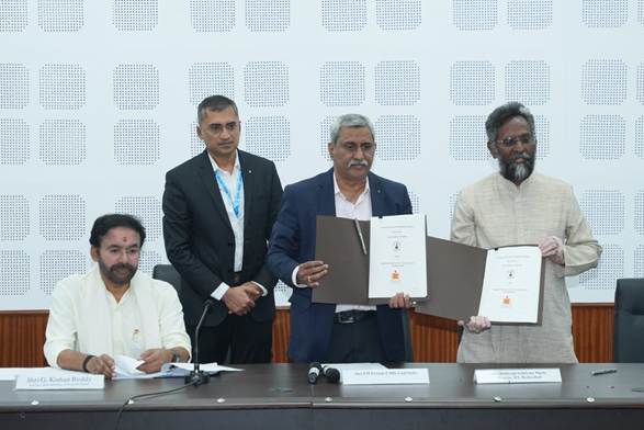
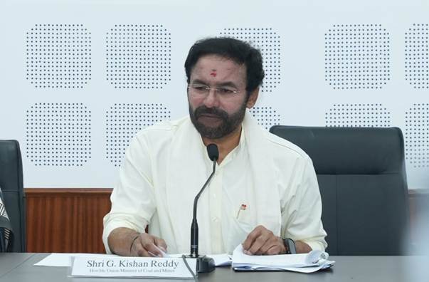
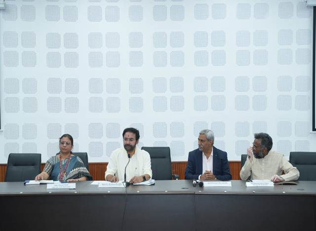


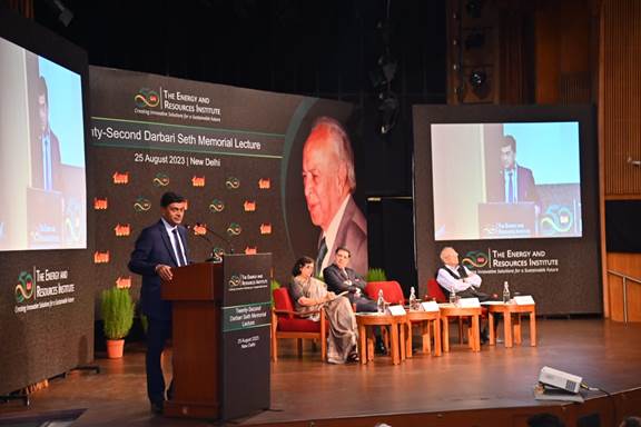
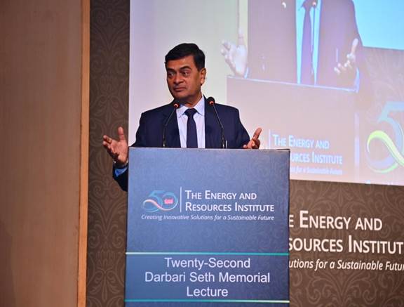
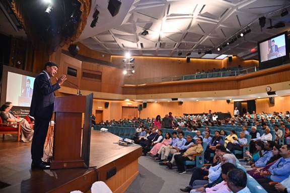
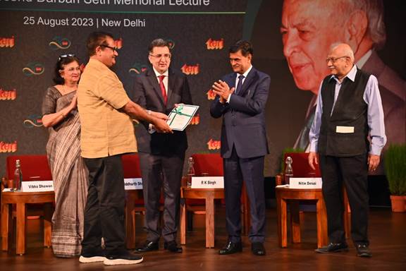

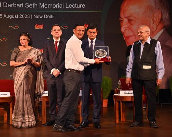
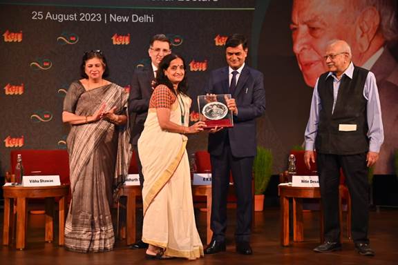
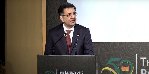
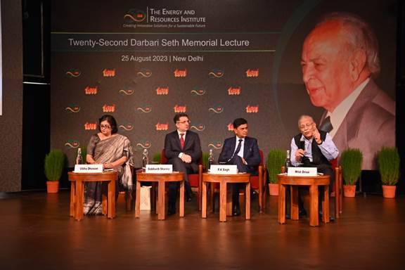
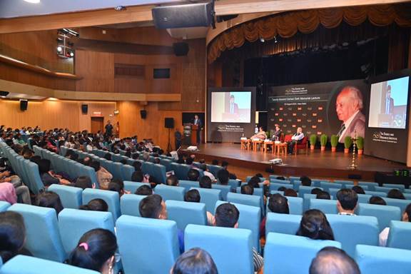
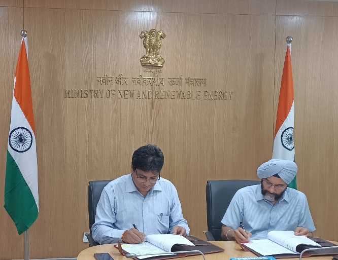
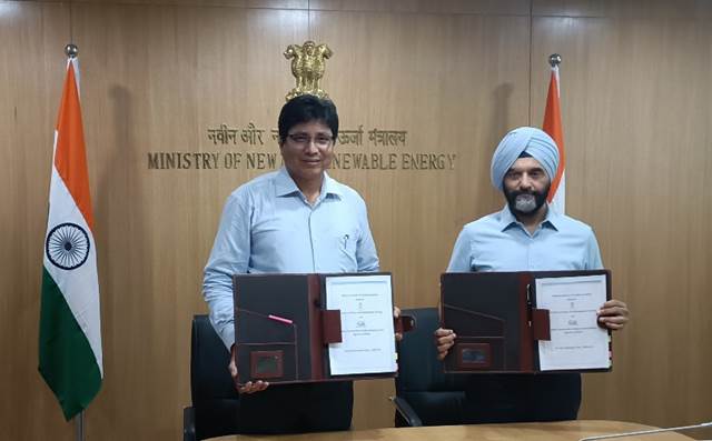
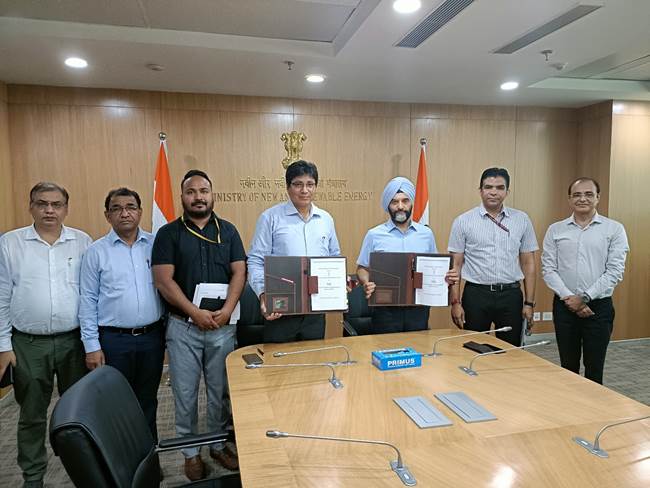
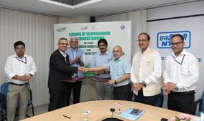
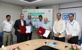


You must be logged in to post a comment.