Monsoons not only give new life to nature, but also drape the surroundings in lively greens. While those used to city life might be unaware of such a thing, India boasts of places that turn lush green during the rainy season. If you are also interested to visit such places, here’s a list of places that turn beautifully green during the monsoons.
Top stunning places for your monsoon wishlist.
Cherrapunji, Meghalaya
Cherrapunji, being the second wettest place on Earth, boasts of pleasant weather throughout the year. When here, you might witness rains coming in with such velocity that you will be drenched in no time. And although it receives a huge amount of rainfall, the beauty of this place is that it does not get flooded. In fact, the place turns livelier during the rainy season, with sounds of chirping and humming of birds and insects, along with the thundering sound of rivers flowing at the bottom of the valley.
Chikmagalur, Karnataka
Chikmagalur is blessed with many attractions that turn magical during the monsoons. Sitting in the lap of Western Ghats, it is one of the places that you will make you crave for more. During this time, you can enjoy a drive to Charmadi Ghat near Chikmagalur; the drive will take you through the Western Ghats, home to many gorgeous waterfalls. Further, the spot is also dotted with tall mountains, vast tropical rain forests, and green valleys, all of which turn alive during the monsoons. You need to visit this spot during this time to believe it.
Bhandardara, Maharashtra
Monsoon is a very pleasant time in Bhandardara, as the Randha Falls and streams and lakes get drenched in monsoon rains. The landscape turns fresh, dewy, and green, making it a lovely spot to visit during this time. Further, Bhandardara being situated in the Sahyadri Mountains of the Western Ghats, it also turns into a haven for hikers and trekkers in and around Maharashtra. However, be sure to avoid the trails that turn slippery during the rains.
Mussoorie, Uttarakhand
During monsoons, Mussoorie turns greener than ever, and makes rains the best time to visit. The crowd too gets thinner at this time as compared to summers and winters. If you visit the Queen of Hills during the rainy season, you get the opportunity to witness the dreamlike setting of monsoon that brings out the best of Mussoorie. The beautiful landscapes, serene ambience, make this spot a must ‘green getaway’ during the rainy season.
Banswara, Rajasthan
Also known as the City of Hundred Islands, it’s a paradise of a place to visit during the monsoons. It got its name from the bans or bamboo trees that once grew in abundance here. Lush green hillocks, scenic surroundings, the presence of youthful lakes and rivers, make this spot so gorgeous that you will forget that you are in Rajasthan. When here, visit the lake banks and Mahi river dam that turn stunning during the rains, thereby making it a dreamy monsoon destination.
“Science has learned recently that contempt and indignation are addictive mental states. I mean physically and chemically addictive. Literally! People who are self-righteous a lot are apparently doping themselves rhythmically with auto-secreted surges of dopamine, endorphins and enkephalins. Didn’t you ever ask yourself why indignation feels so good?”
~ David Brin
Introduction
Doping in sport is a widespread problem not just among elite athletes, but even more so in recreational sports. In scientific literature, major emphasis is placed on doping detection, whereas detrimental effects of doping agents on athletes’ health are seldom discussed. Human growth hormone also increases muscle mass, although the majority of that is an increase in extracellular fluid and not the functional muscle mass.
The term doping is widely used by organizations that regulate sporting competitions. The use of drugs to enhance performance is considered unethical, and therefore prohibited, by most international sports organizations, including the International Olympic Committee.
History
According to the World Anti-Doping Agency (WADA), the term “doping” probably comes from the Dutch word “dop,” an alcoholic beverage made of grape skins that was used by Zulu warriors to make them stronger in battle.
Ancient Greek athletes used special diets and stimulating potions to improve performance, and 19th century endurance athletes indulged in strychnine, caffeine, cocaine and alcohol.
The American specialist in doping, Max M. Novich, wrote: “Trainers of the old school who supplied treatments which had cocaine as their base declared with assurance that a rider tired by a six-day race would get his second breath after absorbing these mixtures.”[8] John Hoberman, a professor at the University of Texas in Austin, Texas, said six-day races were “de facto experiments investigating the physiology of stress as well as the substances that might alleviate exhaustion.”
Effects of doping in sports
It builds muscle but causes abnormal growth, heart disease, diabetes, thyroid problems, hypertension, blood cancers and arthritis. Other adverse effects include joint pain, muscle weakness, visual disturbances, enlarged heart and diabetes.
Other side effects include:
Heart palpitations.Heart rhythm abnormalities.
Weight loss.
Tremors.
Mild high blood pressure (hypertension)
Hallucinations.
Stroke.
Heart attack and other circulatory problems.
Constipation.Skin rash or dermatitis.
Diarrhea.
Dizziness.
Drowsiness.
Dry mouth.
Headache.
Insomnia.
UFC ( Ultimate Fighting Championship ).
In December 2013, the UFC began a campaign to drug test their entire roster randomly all year-round. Random testing, however, became problematic for the promotion as it began to affect revenue, as fighters who had tested positive would need to be taken out of fights, which adversely affected fight cards, and therefore pay-per-view sales.
According to Steven Marrocco of MMAjunkie.com, about 31% of UFC fighters subjected to random testing since the program first started have failed due to using performance-enhancing drugs. That is approximately five failed tests for every sixteen random screenings.
From July 2015, the UFC has advocated to all commissions that every fighter be tested in competition for every card. Lorenzo Feritta, who at the time was one of the presidents of the UFC, said, “We want 100 percent of the fighters tested the night they compete”. Also, in addition to the drug testing protocols in place for competitors on fight night, the UFC conducts additional testing for main event fighters or any fighters that are due to compete in championship matches.
“The unthinkable is that we’re distorting this atmospheric balance. We’re shifting the chemical balance so that we have more poisons in the atmosphere – ozones and acid rain on ground level – while we’re also changing the thermal climate of the earth through the greenhouse effect and – get this – simultaneously causing destruction of our primary filter of ultraviolet light. It’s incredible. Talk about the national-debt crisis – we’re piling up debts in the atmosphere, and the piper will want to be paid.”
~ Michael Oppenheimer
Introduction
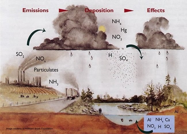
Acid rain, or acid deposition, is a broad term that includes any form of precipitation with acidic components, such as sulfuric or nitric acid that fall to the ground from the atmosphere in wet or dry forms. This can include rain, snow, fog, hail or even dust that is acidic.
Acid rain is caused by a chemical reaction that begins when compounds like sulfur dioxide and nitrogen oxides are released into the air. These substances can rise very high into the atmosphere, where they mix and react with water, oxygen, and other chemicals to form more acidic pollutants, known as acid rain.
It can have harmful effects on plants, aquatic animals, and infrastructure.
Effects of Acid Rain
The ecological effects of acid rain are most clearly seen in aquatic environments, such as streams, lakes, and marshes where it can be harmful to fish and other wildlife. As it flows through the soil, acidic rain water can leach aluminum from soil clay particles and then flow into streams and lakes.
Acid rain has been shown to have adverse impacts on forests, freshwaters, and soils, killing insect and aquatic life-forms, causing paint to peel, corrosion of steel structures such as bridges, and weathering of stone buildings and statues as well as having impacts on human health.
Acid rain also causes the corrosion of water pipes. Which further results in leaching of heavy metals such as iron, lead and copper into drinking water.
Prevention
1. The only precaution that we can take against acid rain is having a check at the emission of oxides of nitrogen and sulphur. 2. We have so far seen the details of acid rain and its harmful effect on animals, plants and the monuments. 3. Being responsible citizens, one should be aware of the harmful effects they cause and of the industries which give out nitrogen and sulphur compound wastes unethically. 4.A great way to reduce acid rain is to produce energy without using fossil fuels. Instead, people can use renewable energy sources, such as solar and wind power. Renewable energy sources help reduce acid rain because they produce much less pollution.
Acid Rain in India
Analysis of rainwater samples from Nagpur, Mohanbari (in Assam), Allahabad, Visakhapatnam and Kodaikanal in the decade 2001-2012 showed a pH level varying from 4.77 to 5.32, indicating that these places have actually been receiving ‘acid rain’. Rainwater with pH below 5.65 is considered acidic.
As energy requirements in India will grow rapidly in tune with the economy, coal dependence is expected to increase threefold over the current level of consumption, making the clouds of acid rain heavier over many highly sensitive areas in the country – the northeast, parts of Bihar, Orissa, West Bengal ,etc ,.
The rains in the Indian Ocean and the Arabian Sea and the Bay of Bengal have become acidic. Studies show the importance to regularly monitor more places for acid rains. But the mechanism to study acid rains is at present inadequate in India. imd stations are not located in the most polluted areas in the country.
From the past two decades , it is stated that the threat of biological warfare is not a myth but a harsh reality of the world . Due to the outbreak , we can recognise the high risk and consequences of bioterrorism.
This editorial provides you the overview of bioterrorism , it’s symptoms , causes , measures and impact on humans in present scenario .
Introduction
A bioterrorism attack is the deliberate release of viruses, bacteria, or other germs to cause illness or death. These germs are often found in nature. But they can sometimes be made more harmful by increasing their ability to cause disease, spread, or resist medical treatment.
Biological agents spread through the air, water, or in food. Some can also spread from person to person. They can be very hard to detect. They don’t cause illness for several hours or days. Scientists worry that anthrax, botulism, Ebola and other hemorrhagic fever viruses, plague, or smallpox could be used as biological agents.
Despite patchy intelligence, France started its own biological weapons programme in the early 1920s. It was headed by Auguste Trillat, an inventive German-educated chemist who envisioned and tested the sustained virulence of airborne pathogens.
The goal of bioterrorism is usually to create fear and/or intimidate governments or societies for the purpose of gaining political, religious, or ideological goals. Bioterrorism may have a different effect on societies than would weapons such as explosives.
Symptoms
The symptoms of exposure to a biological agent might include sore throat, fever, double or blurred vision, rash or skin blisters, exhaustion, difficulty talking, confusion, descending muscle weakness, nausea, abdominal pain, vomiting, diarrhea, and coughing.
History
Historically, biological weapons have been a threat to humans for many centuries. At those times, very crude methods such as fecal matter, animal carcasses, etc. were used to contaminate water sources, but now the concentrated forms of biological agents such as dried spores and genetically modified organisms are available, which are fatal even in minute quantity.
During the Indo-Pakistan war of 1965, a scrub typhus outbreak in north-eastern India came under suspicion. India’s defense and intelligence outfits were alert to the outbreak of pneumonic plague – well known in biological warfare – in Surat and Bubonic plague in Beed in 1994, which caused several deaths and sizeable economic loss.
Prevention
There are some points that you need to consider during the outbreak :
If you become aware of a suspicious substance, quickly get away.
Cover your mouth and nose with layers of fabric that can filter the air but still allow breathing. Examples include two to three layers of cotton such as a t-shirt, handkerchief or towel.
Depending on the situation, wear a face mask to reduce inhaling or spreading germs.
If you have been exposed to a biological agent, remove and bag your clothes and personal items.
Follow official instructions for disposal of contaminated items.
Wash yourself with soap and water and put on clean clothes.
Contact authorities and seek medical assistance. You may be advised to stay away from others or even to quarantine.
If your symptoms match those described and you are in the group considered at risk, immediately seek emergency medical attention.
Follow the instructions of doctors and other public health officials. Avoid crowds.
Replacing traditional sources of energy completely with renewable energy is going to be a challenging task. However, by adding renewable energy to the grid and gradually increasing its contribution, we can realistically expect a future that is powered completely by green energy.
– Tulsi Tanti
A way to live a new life . Without any destruction , without worrying about the future . Live a life where we can grow together , develop a life with renewable resources.
Introduction
A renewable resource, also known as a flow resource, is a natural resource which will replenish to replace the portion depleted by usage and consumption, either through natural reproduction or other recurring processes in a finite amount of time in a human time scale.
When such recovery rate of resources is unlikely to ever exceed a human time scale, these are called perpetual resources. Renewable resources are a part of Earth’s natural environment and the largest components of its ecosphere. A positive life-cycle assessment is a key indicator of a resource’s sustainability.
Renewable resources are an energy source that cannot be depleted and are able to supply a continuous source of clean energy.
Renewable resources also produce clean energy, meaning less pollution and greenhouse gas emissions, which contribute to climate change.
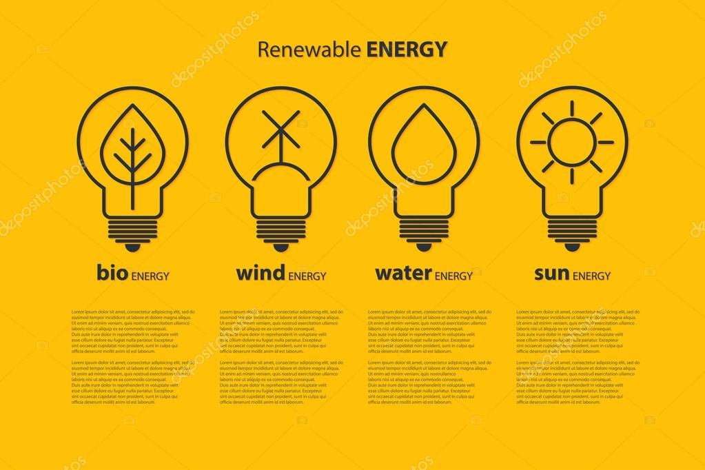
Examples of renewable resources.
Biomass .
Biogas.
Tidal Energy.
Wind Energy.
Geothermal Energy.
Radiant Energy.
Hydro Electricity.
Compressed Natural Gas.
Types of renewable resources.
1) Solar energy. Sunlight is one of our planet’s most abundant and freely available energy resources. 2) Wind energy. Wind is a plentiful source of clean energy. 3) Hydro energy. 4) Tidal energy. 5) Geothermal energy. 6) Biomass Energy.
Impact of renewable resources.
Environmental impact
Renewable energy projects have also contributed in improving environmental impacts such as reduction of carbon dioxide gas, awakening community about the climate change. The study observed very small impacts on the people living in a particular area, tourism, cost of energy supply, and educational impacts. Significant impacts were observed in improvement of life standard, social bonds creation, and community development. They also observed that the renewable energy projects are complex to install and are local environmental and condition sensitive. Their forecasting, execution, and planning require more consideration and knowledge as compared to other projects.
Social impact
These resources also provide social benefits like improvement of health, according to choice of consumer, advancement in technologies, and opportunities for the work, but some basic considerations should be taken for the benefit of humans, for example, climate conditions, level of education and standard of living, and region whether urban or rural from agricultural point of view. Social aspects are the basic considerations for the development of any country. The following social benefits can be achieved by renewable energy systems: local employment, better health, job opportunities, and consumer choice.
Advantages of renewable resources.
Renewable energy won’t run out.
Maintenance requirements are lower.
Renewables save money.
Renewable energy has numerous health and environmental benefits.
Renewables lower reliance on foreign energy sources.
Higher upfront cost.
Intermittency.
Storage capabilities.
Conclusion
Renewable energy is becoming an important resource in all over the world . I do agree that people might exploit the resources for there own benefit . But the government is working on that aspect and trying to provide resources that can help our future households .
There are a lot of different ways of building a prosperous society, and some of them use much less energy than others. And it is possible and more practical to talk about rebuilding systems to use much less energy than it is to think about trying to meet greater demands of energy through clean energy alone.
MEPAP(MULTIPURPOSE ELECTRICITY PRODUCER INTEGRATED WITH AIR PURIFIER)
WHAT MADE ME TO DO THIS PROJECT
I was from a lower middle class family. We suffered many months without electricity and our area is prone to traffic so our area is filled with smoke and dust. Many were suffering from several respiratory disorders due to this dust and smoke. These made me to think of inventing a low cost electricity generator
The growing demand for electrical energy and increasing air pollution around the globe is the main factor that driven my research.
More than 80 percent of our energy today comes from burning fossil fuels, which is both harmful to our environment and unsustainable as well. My invention will help to solve the energy crisis by improving the efficiency of electromagnetic energy-harvesting systems, vibration energy-harvesting systems , wind energy-harvesting systems, thermal energy harvesting system and air cleanser all in a single project.
Due to increase in the carbon dioxide level and other harmful gases specially which are contributing in increase in pollution and global warming, our automobile industries are one of the easy and clear target therefore many researches has been undertaken in this field . Globally, it is estimated that about 1/3 of the total energy is utilized while remaining is rejected as waste heat. The maximum efficiency of an engine is around 25% which means that 75 % of the energy left is wasted in the form of heat from parasitic losses and friction which causes 30% waste in the engine coolant and 40% in the form of gases in exhaust.
The given figure shows the energy distribution in an Internal Combustion Engine.
MEPAP’S AIR PURIFIER
FEATURES AND WORKING
MEPAP AIR CLEANSER IS AN AIR PURIFIER WHICH PURIFIES AIR FROM THE SOURCE (VEHICLES AND FACTORIES EXHAUST) WHERE IT IS PRODUCED.
IT IS MADE TO REDUCE THE AIR POLLUTION
The compact purifier is an apt solution for the increasing pollution. The Active Oxidization Cell with its self-cleaning abilities keeps the purification process on, while the 360º air flow guards us from harmful impurities by distributing healthy air.
Active shield
The purification process eliminates sub-micron respirable particles and infection carrying microbes in the air.
Active Carbon Filter
The most advanced technology filters out bad odor, toxic gases and other harmful gases including VOCs (Volatile Organic Compounds) from the air you breathe in. The carbon filters have excellent absorbent qualities to soothe respiratory discomforts by eliminating irritants in the air.
ICC (Improved Catalytic Converter): Catalytic converters, having expensive metals namely platinum-palladium and rhodium as the catalysts, are fitted into automobiles for reducing emission of poisonous gases. As the exhaust passes through the catalytic converter, unburnt hydrocarbons are converted into carbon dioxide and water, and carbon monoxide and nitric oxide are changed to carbon dioxide and nitrogen gas, respectively. To overcome from cost and reducing the rare metal usage the project made the drive to develop an alternate source of oxidation catalyst for oxidation reaction and thus reduces the NOx and HC emissions. The substrate selected in this project is wash coat technology employed by using the silicon dioxide and alumina with silica. The catalytic converter is constructed with inner/outer shell construction supported with cones and flanges. The initial emission readings are conducted in the experimental engine. This catalytic converter reduces the harmful pollutant more efficiently and at a lower cost than the conventional catalytic converter.
Honeycomb Active Carbon Filter
The carbon filters have excellent absorbent qualities to eliminate repulsive smell, toxic gases and other odor, leaving behind fresh and pure air to breathe.
HEPA (High Efficiency Particulate Air Filter) Type Filter
The HEPA type filter removes airborne pollutants and eliminates ultra-fine particles like bacteria, pollen, and mould, which cannot be done by other air purifiers.
Anion Generator
The technology ensures that the air you breathe has no positive ions, leaving you rest assured of living in a no impurities zone. Negative ions produced by purifier bind themselves with airborne pollutants and removes them from the air thereby creating a fresh and cleaner environment
Air pollution sensors
Air pollution sensors are devices that detect and monitor the presence of air pollution in the surrounding area. They can be used for both indoor and outdoor environments. These sensors can be built at home, or bought from certain manufactures. Although there are various types of air pollution sensors, and some are specialized in certain aspects, the majority focuses on five components: ozone, particulate matter, carbonmonoxide, sulfur dioxide, and nitrous oxide.
FUTURE PLAN FOR AIR PURIFIER PART
Carbon Separator and Collector: Carbon dioxide is considered a major reason for global warming. The element jeopardizes people’s health, threatens national security, and endangers basic human needs. Yet, it also holds great promise as a fuel of the future.
The carbon dioxide splitter, which consists of copper and tin.
The splitter has an atomic layer of tin in order to trap the energy that would be lost if copper is utilized as an electrode. It also has a thin membrane between the cathode and anode to improve the reaction.
The splitter can open windows to solving the problem of storing energy from renewable sources by turning it straight into liquid fuel.
The process of splitting is efficient and carbon-neutral. It is already a well-known method of producing fuel without increasing the level of carbon dioxide in the atmosphere. CO2 is split into oxygen and carbon monoxide.
Carbon monoxide can be incorporated with hydrogen to create synthetic carbon-based fuel. CO2 is taken out of the atmosphere without being put back in, which produces clean fuel.
MEPAP ELECTRICITY GENERATOR GENERATES ELECTRICITY WITH THE HELP OF VIBRATRION(Piezoelectric Materials) AND ELECTROMAGNETIC RADIATION(with the help of MetaMaterials) ELECTROMAGNETIC induction [inductive coupling(power density is proportional to d, q, 1/d^3)] and wind energy( from purifier where mini turbine is connected with dynamo) AND ALSO THERMOELECTRIC ENERGY (power density=25µW/cm^2).
ELECTRICITY from VIBRATRION
MEPAP ELECTRICITY GENERATOR could produce enough electricity from random, ambient vibrations to power a wristwatch, pacemaker, wireless sensor , phones etc..,
MEP are highly efficient at providing renewable electrical power from arbitrary, non-periodic vibrations. This type of vibration is a byproduct of traffic driving on bridges, machinery operating in factories and humans moving their limbs.
In two of the sub generators present in PFIG (Parametric Frequency Increased Generators), the energy conversion is performed through electromagnetic induction, in which a coil is subjected to a varying magnetic field. This is a process similar to how large-scale generators in big power plants operate. It also uses piezoelectric material, which is a type of material that produces charge when it is stressed. This version has applications in infrastructure health monitoring. The generators could one day power bridge sensors that would warn inspectors of cracks or corrosion before human eyes could discern problems.
Power Density= 4 µW/cm^2
MECHANISM AND APPLICATIONS:
It contains a resonator which is used to amplify the vibration source, and a transducer device which changes the energy from the vibrations into electrical energy. The transducer consists of a magnet and coil of a piezoelectric crystal.
A number of crystals can emit an electric current when compressed or they can change shape when an electric charge is employed. This piezoelectric effect is used in ultrasound and sonar devices, as well as energy harvesting.
Piezoelectric generators utilize thin casings or beams made of piezoelectric crystals as a transducer mechanism. When a crystal is placed under strain by the kinetic energy of the vibration, a small quantity of current is produced because of the piezoelectric effect. These mechanisms are generally straightforward with few moving parts, and they have a very long service life, making them the most prevalent technique of harvesting the energy from vibrations. It is fabricated by MEMS process.
This device uses a freely rotating, unconventional brass rotor with an implanted magnet, and multiple PZT beams with a magnet on each beam.
As the magnet on the rotor draws near one of the beams, the magnets repel each other and deflects the beam, pulling the beam in a process that is described as frequency up-conversion. The gradual rate of a rotating wrist is changed into a higher frequency oscillation. This device is more efficient than a standard electromagnetic harvester, as such as those used in self-powered watches.
Another application, which is in the early stages of development, desires to use the vibrations generated during aircraft flight to power the electronics on the plane that currently depend on on batteries. Such a system would produce a reliable energy source, and reduce maintenance, since batteries would not need to be replaced and piezoelectric systems have a long service life. This system uses a resonator, which permits the airflow to produce a high amplitude steady tone. This is the same principle that is used in many wind instruments by converting the airflow furnished by the musician into a loud steady tone. This tone is used as the vibration that is transformed from kinetic to electric energy by the piezoelectric generator
ELECTRICITY from ELECTROMAGNETIC RADIATION:
Electromagnetic energy harvesting based on the “full absorption concept.” This involves the use of metamaterials that can be tailored to produce media that neither reflects nor transmits any power—enabling full absorption of incident waves at a specific range of frequencies and polarizations since the inception of collecting and harvesting electromagnetic energy, classical dipole patch antennas have been used. “Now, my technology introduces ‘metasurfaces’ that are much better energy collectors than classical antennas. microstrip patch antennas areused because of their low profile, light weight, and planar structure for RF harvesting.
Metasurfaces are formed by etching the surface of a material with an elegant pattern of periodic shapes. The particular dimensions of these patterns and their proximity to each other can be tuned to provide “near-unity” energy absorption. This energy is then channeled to a load through a conducting path that connects the metasurface to a Electromagnetic energy collector.
We can also channel the absorbed energy into a load, rather than having the energy dissipate in the material as was done in previous works. Other key applications include “wireless power transfer—directly adaptable to power remote devices such as RFID devices and tags or even remote devices in general.
The technology can also be extended to the infrared and visible spectra
Power Density= 25µW/cm^2.
ELECTRICITY from ELECTROMAGNETIC RADIATION(RF):
Wi-Fi signals are made of radio waves. Receiving antennas can wirelessly harvest electromagnetic radiation in the Wi-Fi (2.4 GHz and 5.9 GHz), global satellite positioning (1.58 GHz and 1.22 GHz), the cellular communications fourth-generation (4G) (1.7 GHz and 1.9 GHz), and Bluetooth (2.4 GHz) bands and convert the energy from these electromagnetic waves to alternating current (AC). The AC electricity is then sent to the rectifier, which converts it to direct current (DC) electricity.
Using a rectifier made from a molybdenum disulfide (MoS2) layer that is only 3 atoms thick. At this thickness, the MoS2 behaves differently than the bulk material — the atoms rearrange themselves when exposed to certain chemicals. This means the material can behave like a switch, changing from a semiconductor to metallic structure. The MoS2 creates what’s called a Schottky diode, a junction of semiconductor and metal. The diode described in their paper can convert signals at higher frequencies because the structure reduces the extra energy stored by certain materials used in electronics, known as parasitic capacitance. The researchers’ design reduces parasitic capacitance by an order of magnitude compared to current flexible rectifiers, meaning they can capture the previously elusive high-frequency Wi-Fi band radio waves.
ENERGY FROM TERAHERTZ(will implement in future.):
Terahertz waves are electromagnetic radiation with a frequency somewhere between microwaves and infrared light. Also known as “T-rays,” they are produced by almost anything that registers a temperature, including our own bodies and the inanimate objects around us.
Terahertz waves are pervasive in our daily lives, and if harnessed, their concentrated power could potentially serve as an alternate energy source. However, to date there has been no practical way to capture and convert them into any usable form.
MEPAP device would be able to convert terahertz waves into a direct current in future, a form of electricity that powers many household electronics.
This design (referred from MIT ) takes advantage of the quantum mechanical, or atomic behavior of the carbon material graphene. They found that by combining graphene with another material, in this case, boron nitride, the electrons in graphene should skew their motion toward a common direction. Any incoming terahertz waves should “shuttle” graphene’s electrons, like so many tiny air traffic controllers, to flow through the material in a single direction, as a direct current.
Rectifiers, devices that are designed to convert electromagnetic waves from their oscillating (alternating) current to direct current.
Most rectifiers are designed to convert low-frequency waves such as radio waves, using an electrical circuit with diodes to generate an electric field that can steer radio waves through the device as a DC current.
Solar Energy:
Photovoltaic (PV) solar panels use the sun’s power to create a flow of electricity. This is the most widely adopted method of harvesting solar energy today. These panels, which range in size from a few square centimeters to a few square meters, are constructed from many PV cells arranged in an intricate matrix. Intuitively, the larger the surface area available for sunlight to penetrate the PV cells, the more solar energy that gets harvested.
Each PV solar cell is generally made up of a compound semiconductor wafer structure, which can either be a monocrystalline or polycrystalline structure. The structure’s two thin semiconductor wafers, one P-type and one N-type, are each grown separately. The two wafers are placed on top of each other, and the natural reaction that occurs between the two semiconductor types creates a depletion zone that reaches an equilibrium point, without generating any electricity. Due to the PV cell, when light photons pass through and connect with the semiconductor wafers, their interaction releases enough energy to create an equilibrium disruption in the depletion region. That action subsequently creates a brief flow of electricity. However, because of the constant presence of light, this interaction occurs continuously and can produce massive amounts of electrical energy.
The power produced by a single photon interaction replicates across the entire surface of the PV cell. It’s compounded into a whole panel of solar cells. This minor interaction in the depletion zone can be repeated and multiplied, resulting in a significant amount of electricity. PV solar arrays, however, produce DC power. To be integrated with modern power transmission technology, such as the outlets in your home, this DC energy must be converted to AC power using an inverter. There are a variety of proprietary iterations of this fundamental technology that seek to optimize the efficiency of each PV cell on a molecular level, the assembly of the panel, and the panel’s ability to be integrated into a larger solar array.
Thin-film solar cell, type of device that is designed to convert light energy into electrical energy (through the photovoltaic effect) and is composed of micron-thick photon-absorbing material layers deposited over a flexible substrate.
Cadmium telluride thin-films have a peak recorded efficiency of more than 22.1 percent (the percentage of photons hitting the surface of the cell that are transformed into an electric current). By 2014 cadmium telluride thin-film technologies had the smallest carbon footprint and quickest payback time of any thin-film solar cell technology on the market. This is the reason why I used Cadmium telluride thin-film in MEPAP.
Power Density= 1000µW/cm^2
Energy Harvesting from a Vehicle’s Exhaust System Using Thermoelectric Generator Module(TEG):
The efficiency in an internal combustion engine ranges from 25% to 35%. About 50% – 85% of the overall energy loss in a combustion engine is heat, which is either cooled away by the vehicle’s radiator or blown out with the exhaust gases. The other losses take place in bearings and gear boxes. This energy is never put into use again and therefore is called “waste heat”. Even if a small fraction of the waste heat could be turned into useful energy again, it would be a step to the right direction of improving fuel economy.
TEG in MEPAP is a solid stated device which works on the principle of ‘Seebeck effect’.
They are found in solar energy systems like solar panels, solar hot water system, biomass power applications, energy power plants and solar pond systems .Installing a TEG with MEPAP is easy and very beneficial as it has some advantages like small in size, it has no vibrations, makes less or no noise while operating, it generally requires less or no maintenance. And major advantage is that it is using free thermal energy and converting into useful electrical energy. A thermoelectric module consists of many thermo elements connected in electrical channel in series to increase the operating voltage and to increase the thermal conductivity they are connected in parallel. According to a research the conversion of this waste heat into electricity results to an increase of fuel efficiency about 20% . A TEG in MEPAP works on the principle of a Seebeck effect. Two metallic strips, made of different metals and joined at the ends to form a loop. If the junctions are kept at different temperatures then there is an electric current in the loop and the emf developed is called the SEEBECK emf or thermo emf and the current can be used to power a load.
The TEG in MEPAP structure is sandwiched with the thermoelectric material which is then sandwiched by the heat exchanger plates at their ends respectively. The two heat exchangers remains at different temperatures, one at high temperature and the other at lower temperature and called the hot side and cold side. A thermally insulated layer is present between metal heat exchanger and material of a TEG in MEPAP. The p type and n type materials are connected by the metal electrically. A TEG in MEPAP consists of a two sides, one is cold and other is hot side. The hotter side derives the electrons in n type leg towards the cold side which pass through the metallic connection and then passes into the p type leg, hence develops current. Larger the temperature difference between cold side and hot side, larger value of emf will produce.
TEG Power Generation Calculation:
The equation involved in calculation of the performance of a TEG
Z = α2/ kR
Z is a figure of merit of thermoelectric material, R is the electric resistivity
k is a thermal conductivity and
α is a Seebeck coefficient which is
α = ∆V / ∆T,
THERMOELECTRIC METALS:
Thermoelectric materials are used in automobiles, power plants, space satellite, etc. Thermoelectric materials can be characterized according to the structure and composition. They can be classified as – chalcogenide, clathrates, skutterudites, half-heusler, oxides and silicides. The most common thermoelectric materials are the alloys of chalcogenide. The calcogenide materials are popular for their use with (Bi2Te3) and (PbTe).Thermoelectric materials made with Bi2Te3, Se and Sb for temperature use are economical. PbTe has better thermo electric properties at temperature range 500-600 ⁰C and has been used by NASA as a radioactive thermo electric generator (RTG’s) . The stability of a TE material is very important as it should not oxidize within the operating temperature when exposed in air .But nowadays; automobile industries are focusing on bismuth telluride for constructing a TEG.
High charge mobility and small band gaps are the properties of two heavy elements Bi and Te and Bulk alloys of PbTe have a zT value of 0.7 at 467 ⁰C. When SrTe and PbTe are doped with Na, zT value was 2.2 at 642 ⁰C .Skutterudites (MX3) have a lower thermal conductivity due to its complex crystal structure has large voids. CoSb3 based skutterudites are versatile in accepting various actinides, lanthanides, alkalis and alkaline earth metals to be used in void filling and thermal conductivity of skutterudites lowers as the size decreases .Compounds of half heuslers are intermetallic compounds which are thermally stable, having high thermal conductivity and corresponding seebeck coefficient. The lattice thermal conductivity of these compounds reduces having nano structures due to phonon scattering. SiGe alloys are used for high temperature applications because of having very low degradation up to 1000 ⁰C. When compared to their bulk alloys, nanostructured SiGe alloys have higher zT value. Bulk Si0.8 Ge0.2 has zT value of 1 and 0.6 for n type and p type respectively. There is an improvement in zT value when nanocomposite thermoelectric materials are used.
HARVESTING WIND ENERGY(HEW Module):
The present invention relates to a combination air purifier and wind generator. The combination air purifier and wind generator includes a wind-receiving unit installed on a central shaft for driving an electric generator mounted in housing, and an air purifier. The wind-receiving unit includes a governor fixed to an upper end of the central shaft, a spherical blower installed in the middle of the central shaft, and planar magnetic rotary plates installed at a lower end of the central shaft for receiving both artificial and natural winds. Lower magnets are attached to the top of the housing while upper magnets having the same polarity as the lower magnets are attached to the bottoms of the magnetic rotary plates to face the lower magnets. The air purifier includes two air inlets; one air outlet; a copper net, a silver net and a hard charcoal/zeolite net disposed within the air purifier for purifying air introduced there into; and a blower interposed between the silver net and the hard charcoal/zeolite net.
Even though the intensity of the wind increases, the shaft of the generator is prevented from being accelerated beyond a predetermined speed so that any damage to the generator can be avoided and its life can be prolonged, and which includes a multi-stage wind-receiving unit for causing the shaft to be easily rotated even with the gentle natural wind and the artificial wind from the blower so as to enhance the electricity generation.
HEW Module consist of electric generator installed in a box-type housing, a central shaft protruding beyond the top of the box-type housing and having a lower end with a gear coupled thereto for engaging with a gear of the electric generator and transmitting a rotational force, and a wind-receiving unit coupled to the central shaft. The wind-receiving unit includes a governor fixed to an upper end of the central shaft, a spherical blower disposed below the governor, and planar magnetic rotary plates disposed below the blower for receiving both artificial and natural winds. The governor includes a plurality of cylinders of which one ends are fixed to the central shaft, a plurality of wind cups of which one ends are slidably installed within the respective cylinders, and springs connected with the inner ends of the wind cups for elastically supporting them. Lower magnets are attached to the top of the box-type housing, and upper magnets having the same polarity as the lower magnets are disposed on the bottoms of the respective magnetic rotary plates to face down toward the lower magnets.
FIG. 1 is a sectional view of a combination air purifier and wind generator according to the present invention.
FIG. 2 is a section view taken along line A—A of FIG. 1.
BRIEF DESCRIPTION OF DRAWINGS:
Hereinafter, a preferred embodiment of a combination air purifier and wind generator according to the present invention will be described in detail with reference to the accompanying drawings.
FIGS. 1 and 2 are sectional views of a combination air purifier and magnet-type wind generator according to the present invention. Reference numeral 1 designates a box-type housing, 2 designates a wind-receiving unit, 3 designates an air purifier, and 10 designates an electric generator.
Each of the electric generators 10 is a conventional model for converting mechanical energy into electrical energy. A shaft of the electric generator 10 is coupled with a gear 11.
The electric generator 10 is installed within the box-type housing 1 made of steel frame and plate, or the like. The gear 11 of the electric generator 10 is engaged with and rotated together with a gear 12 coupled with a lower end of a central shaft 13 which penetrates through the center of a top surface of the box-type housing 1 and is positioned in the box-type housing 1. Thus, the gear 11 connected to components for generating electricity, such as a coil and a magnet that are not shown in the figures, within the electric generator 10 converts the mechanical energy into the electrical energy.
The wind-receiving unit 2 installed on the central shaft 13 includes three wind-resistant bodies: a governor 7 fixed to an upper end of the central shaft 13, a spherical blower 6 disposed below the governor, and planar magnetic rotary plates 5 disposed below the blower 6 for receiving both artificial and natural winds.
The governor 7 fixed to the upper end of the central shaft 13 is a horizontal centrifugal rotary body and includes a plurality of cylinders 73 of which one ends are fixed to the central shaft 13, a plurality of wind cups 72 of which one ends are slidably installed within the respective cylinders 73, and springs 75 connected with the inner ends of the wind cups 72 and inner walls 74 of the cylinders 73 for elastically supporting them.
The blower 6 installed in the middle of the central shaft 13 takes the shape of a sphere defined by a plurality of grouped winglets and can obtain a rotational force even with gentle winds generated in all directions. Further, since the blower 6 is disposed in the middle of the central shaft, it can serve to provide a starting force to the central shaft 13 upon existence of the gentle wind while keeping the balance of the central shaft 13, thereby preventing the central shaft 13 from stopping.
Each of the planar magnetic rotary plates 5 installed at a lower portion of the central shaft 13 is made in the form of a rectangular bucket as shown in FIG. 2. Upper magnets 4′ are attached to the bottoms of the respective magnetic rotary plates. Repulsive forces are produced between the upper magnets 4′ and lower permanent magnets 4 (20,000 gauss or higher) that have the same polarity as the upper magnets and are attached to the top of the box-type housing 1, and thus, a levitation phenomenon occurs therebetween. Accordingly, weights of all the components installed on the central shaft 13 become zero, so that the magnetic rotary plates can be easily rotated even with the gentle wind by means of a rotational action resulting from the repulsive forces between the magnets having the same polarity. Consequently, the rotational ability of the magnetic rotary plates can be improved even under any windy conditions. Particularly, the magnetic rotary plates are constructed to be forcibly rotated with the artificial wind discharged from a blower 36 of the air purifier 3 to be described later, even in the gentle natural wind or windless state.
Moreover, as shown in FIG. 2, the wind cups 72 of the governor 7 and the magnetic rotary plates 5 are staggered so that the wind sequentially and consecutively encounters the wind cups 72 and the magnetic rotary plates 5. Thus, a continuous rotational force is transmitted to the central shaft 13.
The air purifier 3 is fixedly installed on a side of the top of the box-type housing 1 and is Y-shaped by including two air inlets 31, 31′ and one air outlet 32. One of the air inlets 31 is horizontally in line with the air outlet 32 while the other air inlet 31′ is formed to incline upward, so that a wind can be generated due to a change in ambient airflow resulting from drawn air streams and a discharged air stream. Further, a copper net 33, a silver net 34 and a hard charcoal/zeolite net 35 for purifying the polluted air are disposed to be spaced apart from one another at predetermined intervals within the air purifier so that the polluted air is caused to pass through them and to be purified. The blower 36 is interposed between the silver net 34 and the hard charcoal/zeolite net 35 so that the air is forced to be drawn and discharged. Mosquito nets 37, 37′ can be installed at the air inlets 31, 31′ to prevent insects from entering the air purifier.
Reference numeral 8, which has not yet been explained, designates a bearing for ensuring smooth rotation of the central shaft 13.
Next, the operation of the combination air purifier and wind generator according to the present invention will be described.
When the box-type housing 1 of the combination air purifier and wind generator is installed at a desired location such as the interior of a room or a roadside, a no-load state suitable for rotation of the central shaft 13 is achieved by means of the repulsive forces between the upper magnets 4′ in the magnetic rotary plates 5 and the lower magnets 4 attached to the box-type housing 1. Thus, even though a very gentle wind encounters the blower 6, the wind cups 72 of the governor 7 and the magnet rotary plates 5, the central shaft 13 immediately begins to be rotated and is further accelerated by the action of the repulsive forces between the lower and upper magnets 4, 4′. Accordingly, the desired electricity can be easily obtained through the electric generators 10.
In order to reduce loads and cause the rotational speed of the central shaft 13 to reach a normal rotational speed in a short time upon initial rotation of the central shaft 13, the wind cups 72 of the governor 7 are maintained in a state where they are pulled toward the central shaft 13 by the springs 75. The wind cups 72 are kept in the initial starting state without any change in their state so as to facilitate the rotation of the central shaft 13 until rated electricity is provided through normal electricity generation.
The initial rotation of the central shaft is facilitated even with the gentle wind by means of the repulsive forces between the lower and upper magnets 4, 4′, the inward positioned state of the wind cups 72, and the spherical blower 6. Further, the magnetic repulsive forces and the inward positioned state of the wind cups 72 continuously assist the central shaft 13, which has begun to be rotated, to cause its rotation speed to reach the rotational speed at which the desired rated electricity can be generated.
Meanwhile, if the intensity of the wind is increased in a state where the rotational speed of each electric generator 10 reaches a normal rotational speed, the rotational speed of the central shaft 13 is also increased and thus the electric generator may be burdened with an overload.
In order to protect the electric generator 10 against the overload, if the central shaft 13 is rotated with a rotational force larger than a predetermined rotational force, the wind cups 72 of the governor 7 are urged outward from the center of the central shaft 13 by centrifugal forces to reduce its rotational force. On the contrary, if the rotational force of the central shaft 13 begins to be reduced, the wind cups 72 are pulled toward the central shaft by means of the restoring forces of the springs 75 so as to reduce the centrifugal forces. Therefore, it is possible to always maintain the normal rotational speed of the central shaft 13.
Meanwhile, in the very gentle natural wind state or the windless state, the blower 36 of the air purifier 3 is operated using either electric power, which has been generated by the electric generators 10 and then stored, or separate electric power. With the operation of the blower 36, the ambient polluted air is caused to be introduced into the air inlets 31, 31′. This causes a change in airflow thereabouts which in turn generates a wind. The introduced polluted air is purified by passing through the copper net 33, the silver net 34 and the hard charcoal/zeolite net 35, which are disposed within the air purifier. The purified air is discharged and then causes the magnetic rotary plates 5 to be rotated as shown in FIG. 2. As the magnetic rotary plates 5 are rotated, the blower 6 and the governor 7 installed above the magnetic rotary plates are rotated together therewith to increase the rotational force. Finally, the central shaft 13 operates the electric generators 10 so that the electricity is generated.
STORAGE SYSTEMS:
The hybrid energy-storage system(HESS) contains two supercapacitors of different sizes and a switching circuit. An adaptive-learning switching algorithm controls the switching circuit. This algorithm predicts the available source energy and the period that the sensor node will remain in the high-energy area. The algorithm dynamically switches between the supercapacitors according to available ambient RF, Vibration, Solar, EM and Thermal energy. Extensive simulation and experiments evaluated the proposed method. The proposed system showed 40% and 80% efficiency over single supercapacitor system in terms of the amount of harvested energy and sensor coverage.
In a HESS typically one storage (ES1) is dedicated to cover “high power” demand, transients and fast load fluctuations and therefore is characterized by a fast response time, high efficiency and high cycle lifetime. The other storage (ES2) will be the “high energy” storage with a low self-discharge rate and lower energy specific installation costs .
Main advantages of a HESS are:
Reduction of total investment costs compared to a single storage system (due to a decoupling of energy and power, ES2 only has to cover average power demand)
Increase of total system efficiency (due to operation of ES2 at optimized, high efficiency operating points and reduction of dynamic losses of ES2)
Increase of storage and system lifetime (optimized operation and reduction of dynamic stress of ES2)
Energy storage coupling architecture in HESS used in MEPAP:
The coupling architecture in MEPAP consists of two DC/DC-converters. Here the parallel converter topology is very common. The additional DC/DC-converter associated with the “high-power” storage is in charge of the voltage regulation of the DC-bus. It helps to operate the “high-power” storage in a broader voltage band, and hereby the available storage capacity is better utilized.
Frequency decoupling used in MEPAP is well suited for real-time applications. It is accomplished by a simple low-pass filter or by advanced filter concepts based on wavelet or Fourier transform. The low frequency component supplies the set-point value of the power controller of ES2, the high frequency component is covered by ES1.
DESIGNS
PIEZOELECTRIC TRANSDUCER
ELECTRICITY from ELECTROMAGNETIC RADIATION
Metasurfaces
MoS2 layer
RF CIRCUITS
Photovoltaic (PV) solar panel:
Thermoelectric Generator Module(TEG)
STORAGE SYSTEMS
RESEARCH TEST AND IMPACTS
RESEARCH TEST ON PIEZOELECTRIC MATERIAL AND ENERGY FROM VIBRATION:
RESEARCH TEST ON ENERGY HARVESTING FROM EM RADIATION,METAMATERIALS AND RECTENNA:
Output power Usually, the outcome of a WPH system is DC power, which is characterized by load voltage VDD and current IDD. Measuring open-load voltage demonstrates the performance of WPH in general since VDD and IDD depend on load impedance. If the load is a sensor, VDD is more important than IDD while in applications like electrolysis or LED, current is the dominant parameter
Comparison of power-harvesting antenna:
Comparison of voltage multiplier:
R as:
Pr= PtGtGr (λ/4πR)2
where Gt and Gr are antenna gains, and λ is the wavelength of the transmitted signal. The received signal strength, diminishes with the square of the distance, requires special sensitivity considerations in the circuit design. Moreover, FCC regulations limit the maximum transmission power in specific frequency bands. For example, in the 900 MHz band, this maximum threshold is 4 W. Even at this highest setting, the received power at a moderate distance of 20 m is attenuated down to only 10 μW.
(a) The concept of a Huygens’ metasurface [38]. (b) A loaded strip-loop unit cell. (c) A reflection less refracting bi-anisotropic metasurface tested using a quasi-optical system at 20 GHz. (d) Full-wave simulation of reflection less refraction for normal incidence to 71.8 degrees.
(a) A collimating Huygens’ metasurface lens. A ‘spider’ unit cell has been used. (b) Beam collimation in the E-plane at 35.2 GHz. Top view of the metasurface metallization pattern. (c) Concept of a cavity excited metasurface to synthesize arbitrary antenna patterns. (d) Synthesized one parameter Taylor’s distribution with side lobes <-20Db. Sketch of metamaterial converter for the generation of flying doughnut pulses. The metasurface consists of azimuthally oriented dipole resonators arranged in concentric rings. The inset at the bottom left of the figure shows a false color image of a flying doughnut pulse, experimentally generated by a plasmonic metasurface (fabricated by focused-ion-beam milling.
Schematics of TPV (a) and STPV (b) systems. Metasurface emitters are heated with the heat source (TPV) or with solar irradiance in STPV using broadband absorbers and the emission is used to power PV cells.
Waveform-dependent absorber which uses a diode bridge and RC circuit to selectively respond to the envelope of the incoming signal rather than simply its frequency.
Generic representation of a nonreciprocal metasurface, with bias field F0. (b) Magnetless transistor-loaded ring metamaterial particle, mimicking electron spin precession in ferrites, with current J0 operating as the biasing field. (c) Reflective Faraday ring metasurface based on the particle in (b). (Left) Perspective view of the metasurface structure. (Right) Faraday rotation angle versus frequency obtained theoretically from the equivalent magnetic Polder tensor (dashed and solid curves) and experimentally from the prototype shown in the insets (dots) .
(a) Calculated dispersion diagram of a coaxial cable loaded with circular metallic inclusions. (b) calculated effective index of refraction of a parallel-plate glide-symmetric structures .
RESEARCH TEST ON PHOTOVOLTAIC CELL AND SOLAR ENERGY
FF is determined by the relation Vmpp /Voc .
RESEARCH TEST FROM EXHAUST ENERGY(TEG MODULE)
Speed of the vehicle is the most important factor for the power generated by a TEG. For better Performance of TEG, speed of vehicle should be greater. As the exhaust temperature is higher, more energy is available for the conversion into electrical energy. There is increase in optimal length and reduction in optimal width based on dynamic optimization simulations when the Temperature of the exhaust increases.
The efficiency and power of a TEG remarkably depends on the temperature. Given figure shows the temperature of inlet and outlet when the engine is operated between 2500 rpm to 3400 rpm. As the engine speed increases, the temperature difference between the surfaces of TEM increases rapidly, hence the output power also increases.
It was found that there is a possibility of generating 1.4 kW of electricity form the heat recovery system in the exhaust of the car if the power produced by the engine is 150 kW and also found that it is possible to produce electricity of 5.9 MW by a waste heat energy recovery system of 500 MW of gas turbine power plant.
Another experiment has been performed for checking the power output of TEG by changing the speed of vehicle. The speed of the vehicle were 48.3, 80.6 and 112.7 km/hr and the result was the output power increased as speed of vehicle increases correspondingly mass flow rate of exhaust and inlet temperature increased as per the speed. At the speed of 80 km/hr, the power output with 72 mm * 4 mm TEM was 75 W.
Fig1. Variation in temperature due to variation in speed.
Fig2. Variation in power production.
TEG Power Generation Calculation:
The equation involved in calculation of the performance of a TEG is
Z = α2 / kR,
Z is a figure of merit of thermoelectric material, R is the electric resistivity
k is a thermal conductivity and
α is a Seebeck coefficient which is
α = ΔV / ΔT,
T ͞ is the average temperature of cold and hot plate of a TEM and when multiplied by Z it makes it Dimensionless.
ZT ͞ = α2 T ͞ /KR
And
T ͞ = (TH +TC ) / 2
As per the second law of thermodynamics,
ῃ = TH – TC / 2
The maximum efficiency of conversion of a TEG can be found using
The output efficiency of a TEG mainly depends on two variables: the temperature and MFR of exhaust. Maximum power output and corresponding heat transfer can be obtained by maximizing the
MFR ratio. As the size of a TEG increases, the output power also increases.
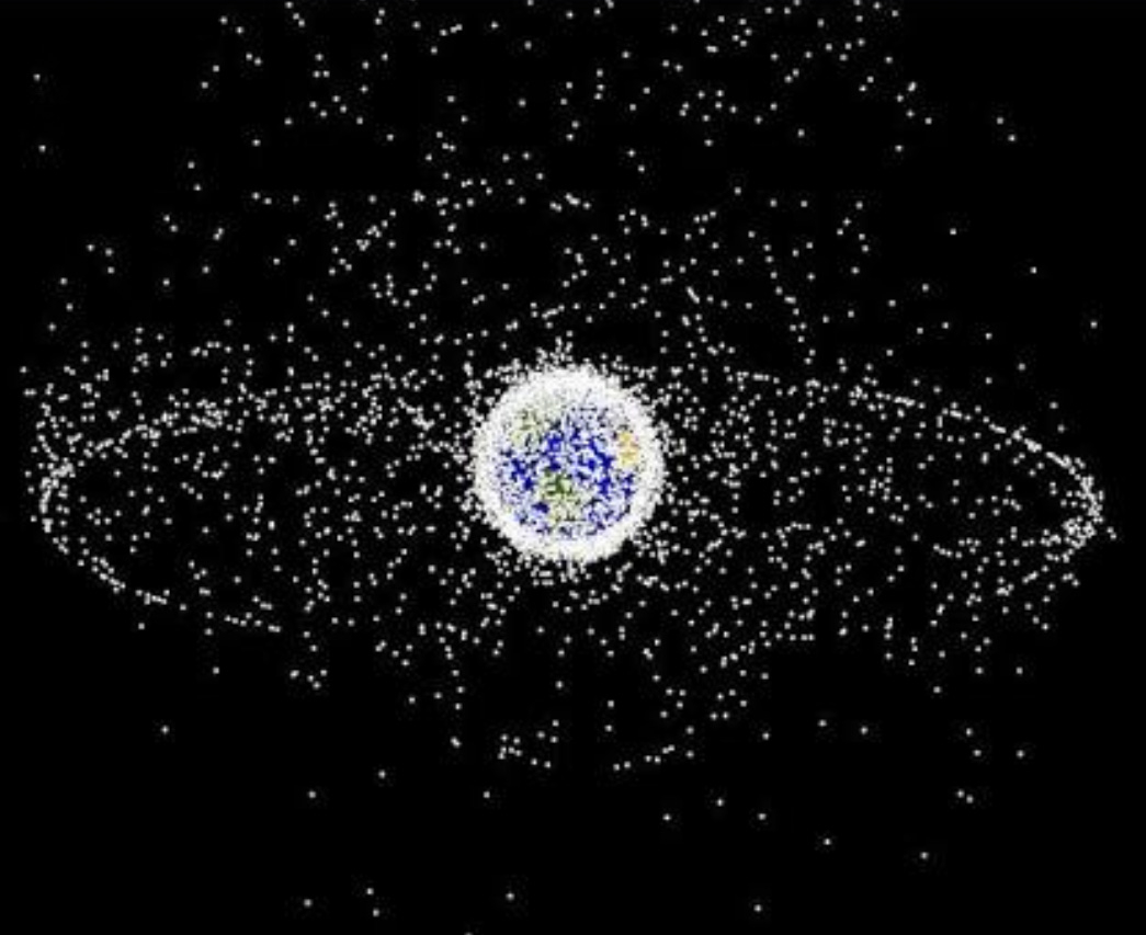
The world has so much problem with the waste production and dumping and landfills. We need more space. Why not send it to outer space? You know take some amount of trash at a time and send it to space and let it go. Sounds easy but turns out it isn’t that easy.
First of all it costs a LOT to send a spaceship into the space. We would need a large number of rocket launches to actually get rid of the insane amount of garbage the world produces(1.2 trillion kg). That way, the rise in air pollution… unimaginable. Also, complex infrastructure requirements! We need a lot more launch pads.
Suppose we do find a way to manage the costs and send a rocket filled with trash to be thrown out in the space. Imagine if some technical issue occurs and it blasts. It would rain burning plastic. Not good for the environment.
Even if we throw it out, the accumulation would make our atmosphere so dense that it would be a toxic world to live in. Also we couldn’t use satellites plus space travel would be tough. What if it comes floating back. Gross sight.
There’s another thing we could do. Burn the trash in the volcanoes. Trash incinerators have filters to filter out poisonous gases. In case of volcanoes filtering is not possible so again toxic world. Besides throwing something in the lava, disturbing the surface, would instantly trigger a chain reaction leading to an explosion. So not an option.
Guess we have to find other sources to convert the trash into some kind of energy. Maybe some day. Till then we need to manage our trash and follow the three R’s. (Reuse, Recycle, Reduce)


You must be logged in to post a comment.